dantwomey said:
The purpose of of cutting a trace for C954 puzzles me. Please refer to the accompanying schematic.
Regards,
Dan
Regards,
Dan
Dan,
The purpose was to cut from 5V supply everything really not needed. Looks like I’ve cut away to much, and now I know the reason why some start-up problems appeared with various combination of 5 and 8V regulators. By tomorrow I’ll connect it back and remove both C954 n C916, while still suppling of motors' driver. Thanks for this remark!
brgds,
dantwomey said:
The purpose of of cutting a trace for C954 puzzles me. Please refer to the accompanying schematic.
On my board (EZ51) the + side of C954 connects to the collector of C902 - that is not what the schematic shows.

John
audio1st said:C954
OK, and the chip is different to the one on the schematic too.
Attachments

I still can't get mine to work with a separate 5V supply 
The 5V is connected to point 5A on the pdf, and I have cut the track between that point and C954. The disc spins but won't read the toc or play.
If I revert to single 8V supply, with 5A re-connected to 5B, all is well again.
Any ideas please?
John
The 5V is connected to point 5A on the pdf, and I have cut the track between that point and C954. The disc spins but won't read the toc or play.
If I revert to single 8V supply, with 5A re-connected to 5B, all is well again.
Any ideas please?
John
I'm not sure how critical it is, but the picture in pdf file shows a different cut off point: the trace is cut not between 5A, but between 5B and C954 (when looking at a picture, just right of the positive pin of C954). The negative pin of that cap is not connected directly to the ground, that's why I decided to leave C954 in a loop, working without schematic has certain advantages ")
When I decided to go back to a single supply, the black wire jumper took care of the cut trace, besides being more solid than very thin original trace.
When I decided to go back to a single supply, the black wire jumper took care of the cut trace, besides being more solid than very thin original trace.
Peter Daniel said:I'm not sure how critical it is, but the picture in pdf file shows a different cut off point: the trace is cut not between 5A, but between 5B and C954 (when looking at a picture, just right of the positive pin of C954).
.
Indeed it is critical! I rejoined 5A to C954 with a wire link and cut the trace right of C954 and all is well, with +5V connected to 5A. See, I'm smiling again
 Thank you Peter.
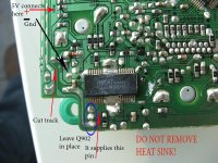
brgds said:As for separate 5/8V, the soultion is: don't cut traces, don't add anything, just remove Q902, C954 and C952, and then put your 5V superregulator somewhere close to receivers, in my case in place of C942.
To do it properly, it's recommended to cut the trace, otherwise your new voltage will be connected with MM1469 internal regulator: http://pdf1.alldatasheet.com/datasheet-pdf/view/82500/MITSUMI/MM1469XH.html
Besides, C954 seems to be needed, C952 is also used for 8V supply smoothing, so unless replaced with other cap, should not be removed. I use 8V regulator followed by 1000uF very close to the board, that's why C952 was removed.
Puffin said:jonners. Are you able to post any pics or a diagram of where you have connected to and exactly which track you have cut.
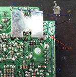
If you look at the picture posted by Audio1st, he has put a red oval around C954. You cut the track below the +ve lead on the left, nearer the edge of the board: You could cut somewhere around where you see the letters R964.
The +5V then connects to point 5A that is shown on the pdf - where the wire link connects (though of course you don't use the wire link).
John
Attachments

Puffin said:jonners. Thanks for that. The -5v goes to the -pin of the cap next to where Q902 was removed?
If you remove the heat sink from the chip to gain access to do the mod, is it neccessary to replace it?
There's no -5V! If you mean 0V/Ground then I think it's probably best if it connects to the same place as the ground of your +8V supply. (Others may disagree?...)
It's possible to cut the trace without removing the heat sink. You would need to replace it if you did remove it, though.
John
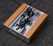
My project is coming to a finish. Thank you all for the inspiration!!! Things to be done :
- top cover
- have front and back chromated
- mechanism for door switch (it should not be possible to operate cd with lens exposed: safety!!!)
- bnc connector
I have a few last questions though before I can continue:
- I want a switch so I can toggle between toslink and bnc, any advise how to implement?
- The digital out now feeds directly into the totx172 (stripped from old Marantz CD60), it works but I guess I need the voltage divider for best operation. Would the suggested divider (392/92) be enough to drive the totx172? Yep, I know I could test myself but I want to avoid extra soldering as the board/traces are a bit flimsy.
- I understand that the bnc connector ground should be connected to the chassis as a best practice. For now only the ground from the powercord is connected to the chassis, should I connect other points of the transport to the ground/chassis? For instance the powersupply ground or the ground from the dig-out on the transport or....
Thanks for any advise!!
Here are some pics.
Attachments
- Home
- Source & Line
- Digital Source
- Finally, an affordable CD Transport: the Shigaclone story