All of this is a bit of nit picking and I don't want to get you nervous that you are doing something wrong, because you are not. It looks like you are doing great work. I just can never leave well enough alone and the engineer in me wants to make it as good as it can be.
When cutting Delrin on a manual machine I don't use coolant. On the NC we use synthetic water based coolant.
I think that you are confused with question 2. Delrin doesn't get brittle. At least that I know of. Acrylic is the brittle one. Delrin is usually suggested as a metal replacement material when weight and cost are an issue. The stuff is tough and can be hammered on without cracking. If you are concerned about cracking with the press fit of the shaft, then Acrylic would be the material to avoid.
The other thing to keep in mind is that if a pro shop is doing this on an NC machine, they will not care about seeing the bore, they will program it and then run it with coolant running. In other words the tool will be cutting in a hose of water and coolant. Heat is really not an issue then.
Simply put, if the amber color is a priority, the go for it. If clear is just as good, the I would say use Lexan. If you are cool with black, I would use Delrin.
2 more parts kits are available. I bought the last EZ31 that had this store (my wife did it for me). So again, if you have problem to find it, send me an email. I'll keep them for two weeks.
CD Clamp
A picture of how to use external Circlip pliers to remove clamp from shaft.
audio1st. did you remove your old clamp to test a Play station clamp? i ask because i tried to remove my clamp but was unable to do it with force levels that i felt wouldn't dammage the drive shaft.
A picture of how to use external Circlip pliers to remove clamp from shaft.
Attachments

CD Clamp
Hi Okapi,
A couple of points about the replacement clamp.
Do you have to drill the 2mm hole the full length of the clamp including the threaded part (the shaft is only 18mm long)?
The original clamp has 9mm of friction fit, the new clamp will have 18mm of friction fit. This will make it very difficult to fit or remove. I say remove because once it is in place, you will not be able to access the motor mounting screws to gain access to the cct board.(the base of the clamp may even touch these screws)..
Should someone search new on stock
TDA1541A-S1 (single crown) DAC's
or
CS8412-CP Receiver (DIL)
You may have a look into the diyaudio marketplace, parts and supplies...
Franz
TDA1541A-S1 (single crown) DAC's
or
CS8412-CP Receiver (DIL)
You may have a look into the diyaudio marketplace, parts and supplies...
Franz
The idea of machining the hole all the way through is so that in one chucking of the part you can cut the CD mounting surface as well and the shaft hole. This will give you best results in terms of runnout and concentricity. If you try and do it in 2 setups the parts will definitely not be as good.
Make it shorter if needed, but the hole through is there for the above reasons. I would suggest getting a space of the right thickness and when mounting the clamp, press it down until it hits the spacer. The mounting height should be pretty important.
Make it shorter if needed, but the hole through is there for the above reasons. I would suggest getting a space of the right thickness and when mounting the clamp, press it down until it hits the spacer. The mounting height should be pretty important.
Re: CD Clamp
The hole needs to be through the full length, otherwise compressed air could make it impossible to push the clamp in.
I calculated the dimensions so the base should not touch the motor mounting screws.
audio1st said:A couple of points about the replacement clamp.
Do you have to drill the 2mm hole the full length of the clamp including the threaded part (the shaft is only 18mm long)?
The original clamp has 9mm of friction fit, the new clamp will have 18mm of friction fit. This will make it very difficult to fit or remove. I say remove because once it is in place, you will not be able to access the motor mounting screws to gain access to the cct board.(the base of the clamp may even touch these screws)..
The hole needs to be through the full length, otherwise compressed air could make it impossible to push the clamp in.
I calculated the dimensions so the base should not touch the motor mounting screws.
clamp aficionado's,
been a little too busy to reply but i have been paying attention to the comments.
removing the motor mount screws will be a little more difficult with the new clamp in place. i am thinking of replacing the screws with bolts to make side access easier. anyone know the screw size?
fitting the clamp on the shaft is something i still need to test, however, i still have not removed the old clamp (going to fabricate a puller) so i am unable to begin testing. i have several ideas on how to approach any potential problems that i will discuss here before taking action if they become relevant. i should have tested fit before i constructed the clamp but i think things will still work out.
as suggested, i am going to use a spacer to put the clamp in the proper position. i was able to find a washer that was exactly 1 mm thick. i just cut an opening in it so it can slide around the shaft.
I just have to say. I love the way that pieces that I don't know or leave out or simply forget to write seem to be filled in by others.
Very cool😎
Very cool😎
germans , beware !
http://cgi.ebay.de/JVC-RC-EZ31B-CD-...ryZ64706QQssPageNameZWDVWQQrdZ1QQcmdZViewItem
there is one available on ebay.de
http://cgi.ebay.de/JVC-RC-EZ31B-CD-...ryZ64706QQssPageNameZWDVWQQrdZ1QQcmdZViewItem
there is one available on ebay.de
I'm in the way to build this TRANSPORT with EZ31 but
how do you make a good finish look with EZ31 control board. (PLAY STOP buttons ?)
if you have pics of finished transport front panel please ?
THANKS 😉
nicK
how do you make a good finish look with EZ31 control board. (PLAY STOP buttons ?)
if you have pics of finished transport front panel please ?
THANKS 😉
nicK
Still two EZ31 left. They won't last much longer. I'll return them at the end of the week, because I'll be gone from home for almost all the month of June.
My Shigaraki is up and running. I had all SMD's removed today and then removed all 'R's in the playermods.pdf. I then ran the wire from 5A to 5B. Although in stock form this transport is not a giant killer in terms of air and treble extension it's still very good with no obvious vices. Very well balanced and listenable. I can't wait to get the BG's in and let it burn in!
Regards,
Dan
P.S. It's currently feeding one of Peter's NOS TDA1543 DACs.
An externally hosted image should be here but it was not working when we last tested it.
Regards,
Dan
P.S. It's currently feeding one of Peter's NOS TDA1543 DACs.

For those of you not going the Bronze and Copper enclosure route, then here is another suggestion.
I have used an old Goodmans unit for this (same chips), but it would work equally well with the JVC.
The transport is directly connected to a couple of bolts bonded to a granite board.
I also replaced the original clamp and motor for a low mass, three point clamp I salvaged from another unit.
I have used an old Goodmans unit for this (same chips), but it would work equally well with the JVC.
The transport is directly connected to a couple of bolts bonded to a granite board.
I also replaced the original clamp and motor for a low mass, three point clamp I salvaged from another unit.
Attachments


These may be cheesy
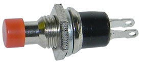
normally open switch
normally closed switch
From MPJA @ $0.29 ea.
Whadaya think?
...100?...200?...
normally open switch
normally closed switch
From MPJA @ $0.29 ea.
Whadaya think?
...100?...200?...
 You give me the idea to change the buttons for "momentary ON push button" for case. (available in ALL COLOR)
- Home
- Source & Line
- Digital Source
- Finally, an affordable CD Transport: the Shigaclone story