I would like the top plate only. Is that possible?
Yes, I think so.
I still wait for some prices and minimum order quantity.
Regards,
Tibi
I would be interested for the top plate too. The black part, not the silver one
Like also ,see the price frist.
We ve been living in the GB constellation lately... Time to get back to discussing improvements and propositions. Unfortunately my experiments have halted for a while now since work is pwning me hard. I hope to get back in track this weekend.
Earlier this week, I came across an article talking about how vibration can induce noise on an oscillating crystal. The issue if you want to look it up is called "Vibration induced phase noise" and it seems to affect crystals, since they are more or less piezoelectric in principle.
Actually the entire vibration analysis made some sense about Peter's initial observations about how the chassis and bolt attachment affected the performance and sound. In a few words my thoughts are that the large metal slab has a high frequency resonance which is more easy to mechanically dampen (for example with wood), and allows some extra mass dampening. At the same time, attaching the turntable with only two bolts keeps the mecha sturdy enough to prevent it from moving around too much making the eye lose focus or track, but at the same time allows some elasticity which but keeps the high frequency vibrations coming from the motors, away from the rest of the devices (crystal or capacitors).
Now how can we make this work even further to our advantage? We all have heard about wood treating caps... well the next step should be treating the crystal. As a first experiment I would suggest some extra mass around the crystal. For example some rubber bands around the metal can. The more the mass, the better it should behave. It should be really easy to test and verify as a theory. And if this proves effective, perhaps moving to more active treatments like wood, or wax or whatever floats your boat as dampening material.
I plan on testing it myself this weekend, but I thought I should share it earlier as a theory since I am pretty curious.
Last edited:
hi Dimkasta,
what about using some blu tacks. heres the link, Amazon.com: Blu-Tack Re-usable Adhesive: Everything Else
can wrap the motor body, crystal, and wherever you think would benefit from it.
what about using some blu tacks. heres the link, Amazon.com: Blu-Tack Re-usable Adhesive: Everything Else
can wrap the motor body, crystal, and wherever you think would benefit from it.
As I said whatever floats your boat.
Bluetack acts more or less like wax, so it should work.
However, I would not use it for initial experiments. It is oily and leaves some nasty residue. I would prefer something cleaner and more easily removable for experimentation. Like a rubber or mdf disc.
Bluetack acts more or less like wax, so it should work.
However, I would not use it for initial experiments. It is oily and leaves some nasty residue. I would prefer something cleaner and more easily removable for experimentation. Like a rubber or mdf disc.
... As a first experiment I would suggest some extra mass around the crystal. For example some rubber bands around the metal can. The more the mass, the better it should behave. It should be really easy to test and verify as a theory. And if this proves effective, perhaps moving to more active treatments like wood, or wax or whatever floats your boat as dampening material.
I plan on testing it myself this weekend, but I thought I should share it earlier as a theory since I am pretty curious.
The simplest way to damp crystal is to use silicone rubber.
Works perfect and improvement is noticeable.
An externally hosted image should be here but it was not working when we last tested it.
Regards,
Tibi
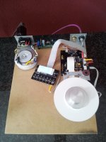
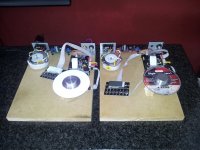
Today came the Mailman and have instantly Vicol MK2 connected.
See how I did it the first Shiga MK2 is playing now: https://www.youtube.com/watch?v=bDGcyDLSogg&feature=youtu.be
Now 2 more to go …
Regards,
Rudy
See how I did it the first Shiga MK2 is playing now: https://www.youtube.com/watch?v=bDGcyDLSogg&feature=youtu.be
Now 2 more to go …
Regards,
Rudy
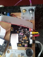
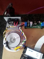
Today the 2nd Vicol Shiga connected and this one now plays also ...
Now the 3rd unpack and try")
Regards,
Rudy
Now the 3rd unpack and try
Regards,
Rudy
Attachments
Last edited:
After some two years of wanting to build a JVC-EZ Shigaclone and collecting various components for it during that time, as well as having scoured the first 150 or so pages of this thread and having taken copious notes, as of tonight mine is finally connected and playing just fine. Currently using the original boombox case to house it all. Cut out the battery holder internal section to open up some room inside the case. Might be able to also fit my Twisted Pear Opus in there, which was the plan. I know that it's not as vibrationally-damped as on a solid base; perhaps someday. Currently have a switch on the front to select between a Riken 75R and a TI 275 "naked" 75R resistor on the digital out, because there was some indication in the thread that there is some audible difference possible. The only thing remaining is a decent 2200uF cap in the power supply. The specified BG is out of my range. Thinking of trying Kendeil who appear to be gaining a following.
Left the speakers mounted inside the case (I know there is the possibility of resonance), hot-glued the cassette door shut, and glued the volume and tuning knobs to the case, as well as gluing the band and source selector switches. Will also glue in the cassette transport buttons after attaining whatever mounting solution is required for the transformer, so it appears visually to be just a boombox. Cheezy, I know. It also takes up space in that nothing may be stacked upon it's curved surface.
One interesting item: upon attempting to unscrew the motor/IC board from the laser assembly, I found that the tiny motor screws were locked and stripping. It turns out that both motors have two tabs on their base which are soldered through-hole on that board, and a quick unsolder had the two easily separated. Scared me for a minute, the thought of attempting to drill them and replace them!
A special thank you to Peter and the other forum members who helped me in this build directly and indirectly, and in sourcing components such as the crystal and some of the BG caps and to those on the original forum who discovered the JVC's usefulness. Some of the photos in this thread answered other questions such as ribbon "polarity" which I'd forgotten to note when I disassembled the unit. Best karma to you all! Happy listening!
I'm currently discussing with manufacturer different options for top and bottom in order to make price more accessible.
In any case, minimum order is 50 pcs. therefore a GB need to be run.
As soon I get complete offer, I'll open a separate thread for GB.
Regards,
Tibi
Hello
and what about side wood panel to have a price more accessible ?
For those still looking for a chassis for their Shiga, maybe there is hope.
Except top, which is laser cut stainless steel, the rest of the box is full aluminum.
Regards,
Tibi
Any update for the price of Chassis ? looking forward.
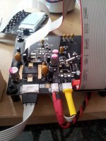
One modification to enhance CD-R, CD-RW and SACD reading.
Recently I got a SACD on which my Shiga refused to read TOC whatever I do.
I started to dig into problem and found one layout problem. This will be corrected in MKII.
C50 - 680pF and Q3 feed pin 59 - LF2 on LA9242. Quoted from datasheet:
"The mirrored surface level is maintained by the capacitor for LF2 (pin 59) ; when a drop in the EFM signal (RFSM
output) reaches 0.35V or more, a high signal is output to DEF (pin 49). If DEF (pin 49) goes high, the tracking
servo enters THLD mode. In order to prevent the tracking servo from entering THLD mode when a defect is
detected, prevent DEFECT from being output by either shorting DEF (pin 49) to GND, or shorting LF2 (pin 59) to
GND."
Therefore, even is not mentioned in any datasheet, C50 must be as close as possible to LC78601 pin - 47.
Q3 must be also as close as possible to C50 in order to avoid any spurious noise to get in.
C45 - 100 pF is there to reject any VHF noise on Q3 and must be as close to Q3 as well.
For me, moving C50 - 680pF and Q3 did the trick and now my unit read TOC without any problem even on the most dirty and old disks which are constantly rejected by a NAIM CD5 XS.
Please note that the pcb trace after LC78601 pin 47 must be cut as well, otherwise will act like a small antenna and this modification will have no effect.
Regards,
Tibi
Hi Tibi,
Any step to step info for this modification ? my Mark I shiga got same problem, want to modify it while waiting for the Mark II to come.
Looking forward for Mark II.
Thanks
with regards
Ang
Any update for the price of Chassis ? looking forward.
Shigaclone chassis will be available with preorder exclusively trough vicol-audio webshop starting with 1st August. Price 225euro ex.VAT and shipping.
The chasis will be 8mm aluminum, top and bottom plastic and 3mm alubond over top.
Regards,
Tibi
Last edited by a moderator:
- Home
- Source & Line
- Digital Source
- Finally, an affordable CD Transport: the Shigaclone story