bf245 digi-lampizator
Hi everyone,
This evening ,after few days of useless attempts to find verifications of the s/pdif improvements with implementation of Mr. Dietmar bf245 jfet digital buffer from Lampizator site I want to share my experience regarding this simple circuit.
The circuit consist of four resistances and one jfet and I encourage everyone to build it since it need only 10 minutes to build and implement it.I connected it directly to 12v gel battery without regulator and resistor are chip 0.6W generic metalfilms and the sound is much more credible than with my diy copper wire wound resistors L-pad used till today in combination with copper-cotton capacitors.I did not tried PI-pad suggested somewhere in the forum jet.
I will report ,if there will be improvements after the copper resistor will be ready to fit after I finish them.
All in all the music is ,as I stated earlier much more credible with less fatigue on long runs.The background silence is much darker and stereo picture and separation of the instruments are done in much cleaner way but not artificial.
I hope this can encourage anyone to try it since there are really little opinions about that circuit on the web and mostly are Lukas Fikus vilification of his work and I suspect the reason is the audio industry truth exposure made by him ,which not everyone likes") .
.
Few years ago I tried tubed digital lampizator and I liked it very much but I was concentrated on transport construction and somehow forgotten it in the process so I decided to try the sand version again.I can tell that I don't want to go back L-pad route anymore.I feel that this doesn't sound only ''different'' from usual resistor solutions and will be able to tell you more after few days of listening ,if anyone is interested ,of course.
Hi everyone,
This evening ,after few days of useless attempts to find verifications of the s/pdif improvements with implementation of Mr. Dietmar bf245 jfet digital buffer from Lampizator site I want to share my experience regarding this simple circuit.
The circuit consist of four resistances and one jfet and I encourage everyone to build it since it need only 10 minutes to build and implement it.I connected it directly to 12v gel battery without regulator and resistor are chip 0.6W generic metalfilms and the sound is much more credible than with my diy copper wire wound resistors L-pad used till today in combination with copper-cotton capacitors.I did not tried PI-pad suggested somewhere in the forum jet.
I will report ,if there will be improvements after the copper resistor will be ready to fit after I finish them.
All in all the music is ,as I stated earlier much more credible with less fatigue on long runs.The background silence is much darker and stereo picture and separation of the instruments are done in much cleaner way but not artificial.
I hope this can encourage anyone to try it since there are really little opinions about that circuit on the web and mostly are Lukas Fikus vilification of his work and I suspect the reason is the audio industry truth exposure made by him ,which not everyone likes
.Few years ago I tried tubed digital lampizator and I liked it very much but I was concentrated on transport construction and somehow forgotten it in the process so I decided to try the sand version again.I can tell that I don't want to go back L-pad route anymore.I feel that this doesn't sound only ''different'' from usual resistor solutions and will be able to tell you more after few days of listening ,if anyone is interested ,of course
.Well, I have a few of the 50V STDs so I tried to sand down the leads. Jarek, I don't know how you may have done it but I got nowhere. So I snipped the leads down and soldered thinner leads that I snipped from one of the smaller 'lytics that I used. Worked great.
I use a Dremel tool for such things. If I didn't have it it, I would have soldered a thinner lead, just like you did.
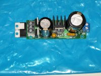
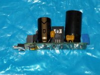
My two 10V supplies are built for the P-A super-regs. I decided to post pics of one of them since it required a bit of special work. I started with Tibi's PS PCB but knew that I wanted to use my custom R-core transformer, which is not center tapped. So I had to turn Tibi's board into something that would support a full wave bridge rectifier. Pics below.
I made one very stupid mistake, however. I accidentally reversed the ripple reject cap which is across the adjust pin. I didn't realize this until I powered it up. Once I saw the Vout was not stable I pulled the power and looked things over. That's when I saw the mistake. I had to cut the old cap out and replace it (that's why the adjust cap is soldered on to the old leads). I hope that didn't damage the circuit.
Oh, you can see I added a bit of Kapton tape to one of the leads on the additional diodes. It was a little to close to the solder pad of the topside diode. Probably would have been fine but I wanted to be safe.
And yes, those are two of my very few remaing BGs doing the filtering work. You might notice that I had to fashion some leads to push out the output terminal block because of the diameter of the 1000uF job. I used the snipped off leads from the BG to do that.
I made one very stupid mistake, however. I accidentally reversed the ripple reject cap which is across the adjust pin. I didn't realize this until I powered it up. Once I saw the Vout was not stable I pulled the power and looked things over. That's when I saw the mistake. I had to cut the old cap out and replace it (that's why the adjust cap is soldered on to the old leads). I hope that didn't damage the circuit.
Oh, you can see I added a bit of Kapton tape to one of the leads on the additional diodes. It was a little to close to the solder pad of the topside diode. Probably would have been fine but I wanted to be safe.
And yes, those are two of my very few remaing BGs doing the filtering work.
You might notice that I had to fashion some leads to push out the output terminal block because of the diameter of the 1000uF job. I used the snipped off leads from the BG to do that.Attachments
Last edited:
Tent Labs XO and C59
Tibi, in the schematic it looks like you're recommending a 1000pF silver mica when using the Tent XO, but there is no recommendation in the BOM. I looked on Digikey and the only SMD micas of that size are huge 2220 parts. Is there a SMD mica that you know of which will work in this location?
Tibi, in the schematic it looks like you're recommending a 1000pF silver mica when using the Tent XO, but there is no recommendation in the BOM. I looked on Digikey and the only SMD micas of that size are huge 2220 parts. Is there a SMD mica that you know of which will work in this location?
Tibi, in the schematic it looks like you're recommending a 1000pF silver mica when using the Tent XO, but there is no recommendation in the BOM. I looked on Digikey and the only SMD micas of that size are huge 2220 parts. Is there a SMD mica that you know of which will work in this location?
Look on Mouser, there must be more options.
You can use any value between 470pF to 1nF to decouple Tentlabs XCO.
Regards,
Tibi
Guys we 've been talking about trying different types of caps on C8, but we have seem to have forgotten about its bypass C9 (as manamanam pointed to me....).
Has anyone tried removing it?
I am back to my 0.1uF FT-3 for C8 since the 0.012uF FT-1 seemed to make CD imperfections quite intolerable, despite the increase in detail.
So now I m wondering if I should remove the smd C9 and simply bypass the 0.1uF FT-3 C8 with the 0.012uF FT-1
Has anyone tried removing it?
I am back to my 0.1uF FT-3 for C8 since the 0.012uF FT-1 seemed to make CD imperfections quite intolerable, despite the increase in detail.
So now I m wondering if I should remove the smd C9 and simply bypass the 0.1uF FT-3 C8 with the 0.012uF FT-1
Look on Mouser, there must be more options.
You can use any value between 470pF to 1nF to decouple Tentlabs XCO.
Regards,
Tibi
Tibi, Mouser shows the same as Digikey. When I did a search by SMD size I found that the 1210 size (there are no 1206 SMD micas on the Mouser site) tops out at 430pF. The smallest 470pF is in a 1812 size.
Last edited:
Guys we 've been talking about trying different types of caps on C8, but we have seem to have forgotten about its bypass C9 (as manamanam pointed to me....).
Has anyone tried removing it?
C9 is connected to pin 11 of the LA9242M, the TA amplifier output pin. C8 is connected to pin 10, the tracking gain time constant setting pin. It doesn't look like a bypass. If you remove C9, pin 11 will connect to nothing.
Tibi, Mouser shows the same as Digikey. When I did a search by SMD size I found that the 1210 size (there are no 1206 SMD micas on the Mouser site) tops out at 430pF. The smallest 470pF is in a 1812 size.
1210 is OK and can be soldered.
Regards,
Tibi
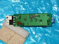
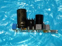
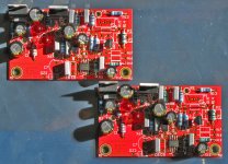
Behold, my two Per Anders SSR01 5V super regulators! They will drive the clock and the digital processing on the main PCB. I have to thank P-A for designing such a nice circuit board, and for being available to answer questions. Beautiful to work on; it was a joy to put together. Hopefully testing will begin tonight.
Attachments
Hi everyone,
Few years ago I tried tubed digital lampizator and I liked it very much but I was concentrated on transport construction and somehow forgotten it in the process so I decided to try the sand version again.I can tell that I don't want to go back L-pad route anymore.I feel that this doesn't sound only ''different'' from usual resistor solutions and will be able to tell you more after few days of listening ,if anyone is interested ,of course
Very interested....
Look on Mouser, there must be more options.
You can use any value between 470pF to 1nF to decouple Tentlabs XCO.
Regards,
Tibi
Tibi, Guido recommended via email a 100nF NPO type for this purpose. I'm not sure what to do.
Tibi, Guido recommended via email a 100nF NPO type for this purpose. I'm not sure what to do.
If you want to have a sensible improvement go for silver-mica.
NP0 will work ok, but 100nF is hard to find and very big for this purpose. In fact NP0 47nF is the biggest value I'm aware of.
Regards,
Tibi
Kemet makes a 1206 100nF NPO that seems to be what Guido was talking about.
C1206H104J3GACTU Kemet | 399-5750-1-ND | DigiKey
Certainly not cheap, though.
C1206H104J3GACTU Kemet | 399-5750-1-ND | DigiKey
Certainly not cheap, though.
Very interested....
Hi Erik,
As I stated in previous post the sound is more precise and credible but it have stolen the bit of magic and ease that simple L-pad posses.The long run listening ease was another brain trick because output level of the dac was slightly quieter with bf245 s/pdif. Unfortunately it was different only.Maybe this is because no regulation is used or it is another semiconductor active part that robbed the music hallucination factor.I remember that tubed version have done that part marvelous so I will report again after tried the tube .Maybe it will make good combination with your system.I have Magneplanars and that pinpoint presentation and credibility of instruments being played led me to listen to sound and less to the music so the conclusion is that valve version might be the ideal solution.Before returning to L-pad I have finally impregnated in parafin ,copper wire resistors so I can't tell that this was useless test ,it have moved me to go further and make some positive changes that had to be done much earlier.Maybe the problem is that I made unfair comparison since I can not make 15kOhm copper resistor because inductance would be to high and was constricted to test the circuit with generic parts on the input of the j-fet.You already know the huge difference in sound between industry and hand made ones and mine are made from non resistive material in bifilar configuration so the battle was unfair for shore.I use them in every place in the system where possible and the improvements in naturalness is stunning.For some this might seem the contradiction but credibility and naturalness in audio differ pretty much ,from my personal standpoint.First one characteristic is making me listen to the sounds and another more the music itself so I took the second route again.Try it yourself ,this is obviously subjective affair ,it take just 10 minutes of time if some 12V DC are ready for use and I have no doubt in that
.Bye
What you call "credible" is the same thing I call "flat dynamics" and "kills the soul of music" - and I run away at the very first sight of it . It is typical of over-engineered systems, with unnecessary gain stages, op-amps, buffers etc., especially where there is some sort of digital DSP involved. Also typical of nude Vishay resistors.
Naturalness, on the other hand, is astonishingly elevated with:
- wood-modding capacitors
- spider-modding the CD platform
- cables that use a thick layer of silk or cotton for insulator and no plastics
- passive, resistor-based pre-amps (as long as those resistors are not nude Vishay)
Alphaigor, you might want to try some resistance wire instead of copper. There are some alloys which make excellent sounding resistors. In fact, most of them sound good, as long as they are non-magnetic. Forgive me for not pointing to a particular one (my resistors are my source of income after all), but like I said most of them yield very good results, and should allow you to achieve much higher resistances.
. It is typical of over-engineered systems, with unnecessary gain stages, op-amps, buffers etc., especially where there is some sort of digital DSP involved. Also typical of nude Vishay resistors.Naturalness, on the other hand, is astonishingly elevated with:
- wood-modding capacitors
- spider-modding the CD platform
- cables that use a thick layer of silk or cotton for insulator and no plastics
- passive, resistor-based pre-amps (as long as those resistors are not nude Vishay)
Alphaigor, you might want to try some resistance wire instead of copper. There are some alloys which make excellent sounding resistors. In fact, most of them sound good, as long as they are non-magnetic. Forgive me for not pointing to a particular one (my resistors are my source of income after all), but like I said most of them yield very good results, and should allow you to achieve much higher resistances.
- Home
- Source & Line
- Digital Source
- Finally, an affordable CD Transport: the Shigaclone story