Tibi, I think this mechanism is toast. The first one of the pair I got in my bundle from you works fine. This one, no matter what I do to adjust the platform height, yields nothing. I can definitely confirm again the solder blob has been correctly removed.
I even tried a third unit I have (a three ball chuck version that I bought before we got everything worked out with the puck) and it too works fine. I'm pretty sure this one is dead. It's unlikely to be an ESD problem as I've treated all three (the two I got from you and the three-ball version) the same way, using an anti-static mat and the same care in handling after the blob was removed.
I even tried a third unit I have (a three ball chuck version that I bought before we got everything worked out with the puck) and it too works fine. I'm pretty sure this one is dead. It's unlikely to be an ESD problem as I've treated all three (the two I got from you and the three-ball version) the same way, using an anti-static mat and the same care in handling after the blob was removed.
Hiostorically, the reasons for a 00 in the display have been a problem with the clock or the solder tabs - and after that the actual mech itself. I had one like that too and chalked it up to learning! At least you've proven its not anything else which in fairness would be harder to fix.
Can't tell you about the Tx location - I just don't know.
Can't tell you about the Tx location - I just don't know.
What sort of field is given off by a toroid, I wonder? I was thinking that maybe I don't want whatever field emissions it gives off being too close to the digital PCB. OTOH, do I wan't it to be otherwise near the transport, potentially affecting its reading/error quality?
Too much pressure on the digital cable?
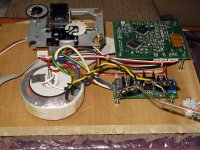
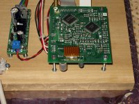
I decided to put the toroid up by the transport mechanism. I might build a copper shield around it, but for the moment I think this is a better place than right by the PCB.
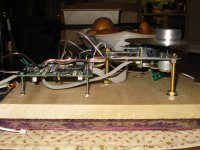
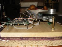
The next question is whether there is going to be too much pressure on the digital cable when it is at the end of a CD. I have two pics attached - you can see that when the read head is at the end of a CD the cable bottoms out on the hardwood base. Will this put too much counter pressure on the head, leading to a higher incidence of read errors as it progress across to the end of a CD?
I decided to put the toroid up by the transport mechanism. I might build a copper shield around it, but for the moment I think this is a better place than right by the PCB.
The next question is whether there is going to be too much pressure on the digital cable when it is at the end of a CD. I have two pics attached - you can see that when the read head is at the end of a CD the cable bottoms out on the hardwood base. Will this put too much counter pressure on the head, leading to a higher incidence of read errors as it progress across to the end of a CD?
Attachments
I seem to remember (but can't find) a discussion about twisting the wires going from the PCB to the mechanism. Did we decide if individually twisting each of the three pairs of wires made any difference to the sound?
In my experience the sled motor circuit does not like added inductance.When I have used ribbon cable everything was fine.When I made longer cable ,until I twisted the poles together I got strange jittery sound coming from loudspeakers.If you use any ribbon cable where individual poles are not separated it will be OK since by given construction the inductance is low.I am using around 0.5m of magnet wire so by twisting them together I get pretty capacitive cable so the length isn't problem regarding inductance and everything sound like there is no three times longer motor cable than usual.I never twisted the short run of cable ,just used short ribbon two poles.
As Dimkasta stated additional capacitive filtering might be useful but test have to be done.I hope this help.
I have exhausted all possible combos of 2 mounted/tested kits and 4 transports. I couldn't get any one of them to get pass 00 ..... Tested with pressed CD's only, so not CDR issue for sure. Adjust the cd table higher and lower also had no luck. Any suggestion what to look for next?
Thanks,
Thanks,
In my experience the sled motor circuit does not like added inductance.When I have used ribbon cable everything was fine.When I made longer cable ,until I twisted the poles together I got strange jittery sound coming from loudspeakers.If you use any ribbon cable where individual poles are not separated it will be OK since by given construction the inductance is low.
Something like this?
135-2406-306 - AMPHENOL SPECTRA-STRIP - RIBBON CABLE, 6COND, 24AWG, 300V | Newark
A slight good news, I dug out a 3 point transport that I ordered some time ao. It worked and finished reading the TOC almost instantly. So, I can focus on the transports now ...I have exhausted all possible combos of 2 mounted/tested kits and 4 transports. I couldn't get any one of them to get pass 00 ..... Tested with pressed CD's only, so not CDR issue for sure. Adjust the cd table higher and lower also had no luck. Any suggestion what to look for next?
Thanks,
My "stock" Shiga so far
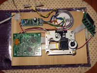
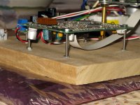
Okay. I decided to post some pictures of what I'm calling my "stock" Shiga. This is the ready-made set of parts I got from Tibi. I completed the layout and the wiring and decided to take a few images before starting on the enclosure.
The enclosure will be made of 1/4" red oak for the sides and the back, and 1/4" poplar for the top with braces on the underside to minimize resonance in a sheet this size. You can see in the last couple of pictures the heat sink I got for the LA6541. It's from Masscool; a bit too big for the chip but it has an adhesive back and it works (convenient). Ignore the temporary terminal strip to bring in the AC power. That will be replaced with an IEC inlet, fuse, and switch when the panels are in place. The digital out will be RG187 going to an Amphenol BNC.
I intend this version to be my stock reference, and the second one to be my custom hot-rodded job. I'm going to live with this a bit as I slowly build up the second version.
Attachments
Nice and Tidy work.
The way you want to go ahead with a second one is the way to go.
Mind you if you modify succesfull you should actually imply it in your stock transport as well (one mod at a time) in order to always have an optimal sounding reference...anyway that is how I build it brings me much info....just a tip")
The way you want to go ahead with a second one is the way to go.
Mind you if you modify succesfull you should actually imply it in your stock transport as well (one mod at a time) in order to always have an optimal sounding reference...anyway that is how I build it brings me much info....just a tip
Yes ,this is good.You can also use twisted pair wires from UTP or take any solid wire cable and twist it much tighter than stranded cable.
Yes ,this is good.You can also use twisted pair wires from UTP or take any solid wire cable and twist it much tighter than stranded cable.
Thanks. I'll give this stuff a try, as I had to buy a couple of remaining parts anyway from Newark. Let you know how it goes.
Nice and Tidy work.
The way you want to go ahead with a second one is the way to go.
Mind you if you modify succesfull you should actually imply it in your stock transport as well (one mod at a time) in order to always have an optimal sounding reference...anyway that is how I build it brings me much info....just a tip
Thank you Erik. I was going to pull out my old spool of lacing cord to lace up the cables going to the transport, but I just didn't feel like it when the tie wraps were so close.
Right now it's playing Tibi's test CD in Repeat mode to give it a good running.If you can provide any guidance on the grounding scheme I'd appreciate it.
Just a note on the ebay mechas. The board and motor markings are quite different from those on Tibi's kit.
Sonically the ebay ones seem to have more distortion across the freq spectrum... It was just a brief test though. I m currently out of town, but I ll post some more when I get back
Sonically the ebay ones seem to have more distortion across the freq spectrum... It was just a brief test though. I m currently out of town, but I ll post some more when I get back
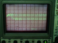
If you have a scope, write a disk with my test cd vicol audio : support, play trak 13 in loop and have a look on LA9242M pin 41. Post a picture here.
Regards,
Tibi
Tibi, this was difficult to do, but I think I have a picture of what happens when Track 13 palys. I had to hit the "Auto" button on my Tek 2465A in hopes that it got what you need. I also had to really play with the levels and contrast on the image to get it to show up (it's fine on the 'scope display but I had to use flash to get the image, so it's a bit washed out). I placed the probe on the chip side of C41 and the ground on the digital out "-" terminal.
Attachments
- Home
- Source & Line
- Digital Source
- Finally, an affordable CD Transport: the Shigaclone story