Tibi, I've started putting my ready mount version of the Shigaclone together. The first thing I did was wire up the transformer and PS board as shown in the instructions. When I plugged it in, I got 7.90 VDC at the output of the PS board, but the LED is not lit. I'm reading 12.6 VDC in one direction across the LED and 9.60 VDC in the other.
A the input to the PS board, I'm showing from Brown to White to Blue - 0 -11-22 VAC,
When I lightly touch the outer side of the LED (the one closest to the edge of the board) with a DMM probe I see the LED flicker slghtly.
Can anyone help? Tibi, I examined the board very carefully and there is definitely no resistor to ground after the LED.
Can anyone help? Tibi, I examined the board very carefully and there is definitely no resistor to ground after the LED.
If there is no resistor this means if you solder one of 330...470 ohm the LED will shine .
If there is no resistor this means if you solder one of 330...470 ohm the LED will shine .
Yes, that would be the thing to do. I have no SMD resistors on hand, though. I'd have to hack in a resistor with axial leads I guess.
But I am hoping for some additional info on what esle to check on the PS to make sure nothing else is wrong. For example, I don't see any resistor in both the R50 and R52 positions (with one of them being for the LED as previously discussed).
R50 and R51 are for LT1086 only and NOT used with L7808 .
Only R52 is the LED resistor .Some say that the PS sounds better without LED connected .
Value at the output is ok for your PS.
Guys can you please advise if this is a correct replacement for the mechanic?
SF-P101N CD Mechanism SFP101 16 Pins Sanyo Philips Alba | eBay
SF-P101N CD Mechanism SFP101 16 Pins Sanyo Philips Alba | eBay
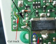
@Peter: Q902 is in place, trace cut and checked several times. Still no reaction... What could be the next step to look?First, I would go back to original setup and see if the transport still working properly.
Didn't have to do that because I got it working after some careful magnifying glass examination. Inadvertently I had also cut the trace marked yellow in the pic. Just a tiny move with the Xacto knife...
Now I am a happy camper!
@secanbj: Thanks for your input... Hope its actually less than 150mA. Cab someone confirm?
Attachments
Last edited:
I note in the instructions a heatsink is recommended for U2. I've been wondering how effective this can be, since U2 is on what in most assemblies will be the underside of the main PCB. How is the heat supposed to convect off the sink if it's covered by the PCB?
Can anyone spare one (or two as I have two PCBs) of the recommended Fischer Electronik heat sinks? There is a $20 freight charge to order these parts through Newark (in the U.S.). $20 is a lot of money for a $1.70 part.
Guys can you please advise if this is a correct replacement for the mechanic?
SF-P101N CD Mechanism SFP101 16 Pins Sanyo Philips Alba | eBay
dimkasta,
Yes ,the 16 pin is our laser.If I understood well you need only the motor.You can pull it out from some non working boom box.Ask for them in local RTV service shop.Many of them use same motors with long shaft like our is.I can present you one motor but I am afraid that the shipping cost from Croatia would be on pair to Ebay seller cost altogether with mechanism and above all you get a laser extra.If you want I can check in the post office the shipping rate and send it to you if it is reasonable.
Thanks guys. I wonder if Tibi is leaving out R52 based on some listening tests?
7.90 VDC seems a little low, doesn't it? That's without the output even connected to anything. What are others getting from the PS output?
I have not tested yet with and without R52.
7.90V for PS is OK.
Regards,
Tibi
I have not tested yet with and without R52.
7.90V for PS is OK.
Regards,
Tibi
Okay Tibi. What is the allowable range for the output of the PS to run things properly?
Thank you very much for your offer
No need for that. As you said, the postage cost should be bigger than the mechanism itself.
Plus I m doing some experiments with ebony and graphite for a new platter, so I will need a few more mechanics for dissecting
I agree on that
 .Spare parts are always welcome
For anyone in the U.S. looking for a heatsink for U2, the Masscool VF1-H looks like it will work. I measured the chip and the VF1-H will fit, although it's a bit wider than U2 (but still seems like it should work okay). They can be bought pretty cheaply here, and it beats paying $24 to get the recommended Fischer sinks from Farnell UK.
Okay Tibi. What is the allowable range for the output of the PS to run things properly?
This is given by LA6541 voltage range operation. According to datasheet this can be between 5.6V and 13V, so 7.90V is more than OK.
You can go higher by using a 7812 regulator, but the power dissipated by LA6541 and 2SB746 will increase. Both will need, for sure, a heat-sink.
Regards,
Tibi

- Home
- Source & Line
- Digital Source
- Finally, an affordable CD Transport: the Shigaclone story