On a slightly more technical note, is there any way to adjust the contrast of the LCD display.
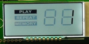
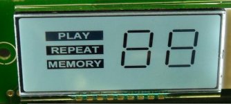
The first image is taken perpendicular to the screen, the second off at about a 15 degree angle.
When looking directly at the screen, the segments which are not active are still quite visible. It does not take being very far off perpendicular to the screen for the image to lose contrast completely.
The datasheet is not very helpful here.
Thanks.
Steven
Attachments
Steven,
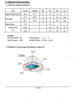
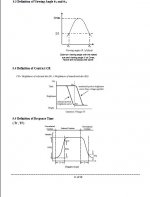
Have attached few more screen shots from LCD datasheet.
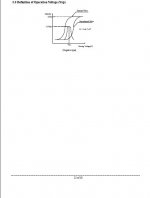
As you can see from the first image, the operating voltage is between 4,5 and 5,1 V. That means we are running the LCD near to maximum. This is one reason for saturation. Yes, I know it´s my fault and it may considered as a design flaw.
The workaround:
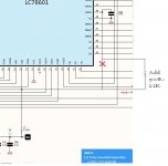
- you may adjust the contrast by placing a resistor at LC78601 pin 40.Use a value between 500ohm and 2K2 or a pot.
- you may adjust the backlight by placing a 500ohm pot in P1 position.
Regards,
Tibi
Have attached few more screen shots from LCD datasheet.
As you can see from the first image, the operating voltage is between 4,5 and 5,1 V. That means we are running the LCD near to maximum. This is one reason for saturation. Yes, I know it´s my fault and it may considered as a design flaw.
The workaround:
- you may adjust the contrast by placing a resistor at LC78601 pin 40.Use a value between 500ohm and 2K2 or a pot.
- you may adjust the backlight by placing a 500ohm pot in P1 position.
Regards,
Tibi
Attachments
any news about the pucks?
There have been two version for CD puck. One low cost using magnetic powder which didn´t worked as expected and one high cost using an Al nonmagnetic puck.
I expect to test Al nonmagnetic puck at the end of this week.
Regards,
Tibi
Thank you for the information on the LCD.
Cut trace carrying V4 to Pin 40 (at pin 40). Insert a resistor (or 500R plus 2K pot in series) from V4 to Pin 40.
Because the resistor is in series with the voltage source it drops the voltage. Best to insure the bypass cap is located on the pin 40 side of the resistor.
Cut trace carrying V4 to Pin 40 (at pin 40). Insert a resistor (or 500R plus 2K pot in series) from V4 to Pin 40.
Because the resistor is in series with the voltage source it drops the voltage. Best to insure the bypass cap is located on the pin 40 side of the resistor.
Attachments
Tibi,
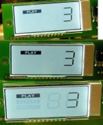
That works great. Even in the third shot at over 45degrees it is still better than it was.
It actually looks best slightly off center.
Top image straight on.
Middle image at about a15 degree angle.
Bottom image at about a 45 degree angle.
I'll measure the value tomorrow and post it. I need to take it back to the solder station to fix it properly.
Attachments
Hi Tibi,
is the the workaround for the display done to all the mounted and tested shiga before they are shipped out?
thanks,
johari
is the the workaround for the display done to all the mounted and tested shiga before they are shipped out?
thanks,
johari
Steven,
Have attached few more screen shots from LCD datasheet.
As you can see from the first image, the operating voltage is between 4,5 and 5,1 V. That means we are running the LCD near to maximum. This is one reason for saturation. Yes, I know it´s my fault and it may considered as a design flaw.
The workaround:
- you may adjust the contrast by placing a resistor at LC78601 pin 40.Use a value between 500ohm and 2K2 or a pot.
- you may adjust the backlight by placing a 500ohm pot in P1 position.
Regards,
Tibi
Tibi,
That works great. Even in the third shot at over 45degrees it is still better than it was.
It actually looks best slightly off center.
Top image straight on.
Middle image at about a15 degree angle.
Bottom image at about a 45 degree angle.
I'll measure the value tomorrow and post it. I need to take it back to the solder station to fix it properly.
This LCD was designed in mind with a film filter in front by the color the user want (hence the white color for backlight) , but this little mod is the way to to be done for all Shiga 2012 from Vicol audio , in fact is the only way to set the contrast to the LCD.
@ The Gimp : best is to measure pot+resistor value and replace with a smd resistor on board , but I think you already intended to do so.
Best regards.
Last edited:
Yes danzup, thanks.
I changed it to a 1.3K smd resistor today with a 0.1uF cap from pin 40 to pin 39 (gnd), and will retest tonight.
I will also use the pot in my other board when I have it finished (waiting on parts ) and see if I get about the same value.
Fortunately there is a via close to the pad and it is a simple fix to cut the trace from via to pad and insert a 0603 resistor (0805 works but is large).
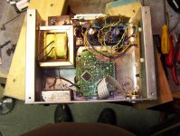
Finally got my Shiga boxed up. Used Starget and Oscon combo for the caps. I went with the minimal upgrades to keep things simple. Case is made from some 3/4 inch aluminum channel. The feet are temporary until I can find something that looks better.
Attachments
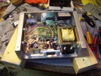
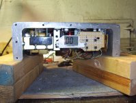
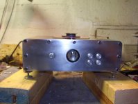
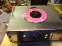
Thanks Gimp. I have three more chunks to make a matching set. One for preamp and two for monoblocks. I did all the machining the hard way, by hand. The cutout for the cd mechanism was done with a hole saw, a hacksaw and hand files. Then I recessed the bottom by drilling a hundred holes and using a drill press with a 3/4 inch milling bit. I clamped the chunk to the table and cleaned out one spot at a time. Tedious but it worked great. The finish was done by belt sanding with 120 grit and then using a palm sander with decreasing grits up to 600. I finally wet sanded using 1000 and then 1500 and then polished with mothers mag wheel compound. It is almost mirror finish in person but I thing there would be another couple of hours of 1500 grit or higher wet sanding to get it there. The buttons were made from 1/2 inch aluminum dowel that I cut to length and then put in the drill press and dropped lightly onto emery cloth to get a nice finish on the end. The results are fairly stunning but fingerprints are a huge problem. ( :
I would appreciate if any technical questions are addressed on the new thread http://www.diyaudio.com/forums/digi...gaclone-create-killer-high-end-transport.html
Thanks & Regards,
Tibi
Thanks & Regards,
Tibi
Goods arrived yesterday. Much thanks Tibi !
A question : some cd's play not very well ( scratch... not fluid ... ) : must the focus be adjusted? I have tried other lasers and they are all different : some of them don't even read the cd's. So what could be the problem?
But the sound is very good after a little burn-in.
A question : some cd's play not very well ( scratch... not fluid ... ) : must the focus be adjusted? I have tried other lasers and they are all different : some of them don't even read the cd's. So what could be the problem?
But the sound is very good after a little burn-in.
- Home
- Source & Line
- Digital Source
- Finally, an affordable CD Transport: the Shigaclone story