Thanks Peter!
Ya I know, I only have a cheap camera, well it's my little girsl one.
What bugs me more is the green transformer wire (GND), should it also be connected with the CT?
BTW, what size and particular type of fuse do you suggest when project is final?
I appreciate...
Ya I know, I only have a cheap camera, well it's my little girsl one.
What bugs me more is the green transformer wire (GND), should it also be connected with the CT?
BTW, what size and particular type of fuse do you suggest when project is final?
I appreciate...
thread for diy bybee
http://www.diyaudio.com/forums/showthread.php?s=&postid=1791544#post1791544
here is my very neat and smartly laid out shigalone power supply with the piezobees incorporated
http://www.diyaudio.com/forums/showthread.php?s=&postid=1791544#post1791544
here is my very neat and smartly laid out shigalone power supply with the piezobees incorporated
Attachments
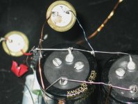
Peter Daniel said:The green wire does not need to be connected to CT, but needs to be connected to a chassis. Then you have the option of connecting CT to a chassis as well; either directly or through 10R or similar value resistor. I'm using 2A SB fuses.
Hi Peter, all!
1.- I don't see anyone (yet in pictures) using green (earth GND) between PS and transport, why? Is it a reason for keeping ground loops out? Isn't that unsecure?
2.- You suggest the option of having the CT connected to chassis, what is the advantage, inconvenient? What have you done?
3.-For the PS section I was wondering, is it better to group voltage regulation components close to the transfo in an enclosure or far from it apart (ex: in the CD transport chassis like you)? In pictures, I see both.
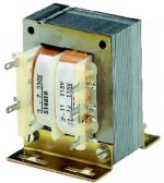
4.-Do all laminated core transfo hum? The one I have in hand hums a bit and I was wondering if it was normal.
Have a nice weekend, thanks.
")
1 You need to ask AndrewT, he's an expert on that matter.
2 I don't see much advantage, it's mostly done for safety reason. I didn't ground my chassis, but transformer/mains voltages are in a separate enclosure which is grounded.
3 It's best to keep rectifiers close to transformer and regulators close to a circuit, if using separate PS.
4 They usualy hum, the amount of noise may depend on mechanical installation and on the amount of DC in your mains.
leoparleur said:Hi Peter, all!
1.- I don't see anyone (yet in pictures) using green (earth GND) between PS and transport, why? Is it a reason for keeping ground loops out? Isn't that unsecure?
There's indeed a good reason for that. The most important reason is the "appliance class" as specified by IEC. This has to do with electrical safety and depends on the strength of electrical insulation (please read this wiki for explanation). The boombox came with a 2 conductor power cord, and therefore will be class II (the label on the back will probably show the European double square symbol), no earthing is required.
Another good reason not to use earthing is the fact that protective earth (PE) can be very polluted, you don't want this pollution to find its way into the chassis. That's probably why most audio and video appliances are constructed for class II compliance. Note: class I appliances must be earthed for safety reasons, whether you like it or not.
The pollution of PE can be so bad that buildings in which electronics are manufactured have a separate earthing system for the EPA-zone (EPA = Electrostatic Protected Area). This earth is often called "clean earth". "Clean earth" and PE are connected at one point only (just like digital and analogue GND are also connected at one point only).
Note: earth (UK) = ground (US). Do not mistake "signal ground", "chassis ground" and "earth ground" for eachother, even though they may be connected.
2.- You suggest the option of having the CT connected to chassis, what is the advantage, inconvenient? What have you done?
It's the signal ground of the circuits, usually that is connected to the chassis.
leoparleur said:
Hi Peter, all!
4.-Do all laminated core transfo hum? The one I have in hand hums a bit and I was wondering if it was normal.
Have a nice weekend, thanks.
If the plates are screwed (in the corners) instead of welded you may want to (re) tighten them again...often the number one cause for excesive hum.....
The laminations are not welded, that would negate the purpose of lamination: to prevent high losses due to eddy currents. Every laminate should be insulated from the other. Another wiki.
It's my experience that square transformers usually have a louder hum than toroids. That also goes for pcb-transformers that are fully covered with resin. My CD-player and DAC together have 5 square pcb-transformers that hum loudly. The boombox transformer is very quiet and so are the toroids in my amp and headphone amp.
It's my experience that square transformers usually have a louder hum than toroids. That also goes for pcb-transformers that are fully covered with resin. My CD-player and DAC together have 5 square pcb-transformers that hum loudly. The boombox transformer is very quiet and so are the toroids in my amp and headphone amp.
There are trafo''s where they use no screws I do not know how the fix them. (looks like a weld but okay)..but maybe Jitters knows.......I have no idea...all I know is they do not use screws so there is no possibility to tension them...usually the fixed ones are the el cheapo''s
jitter said:
There's indeed a good reason for that. The most important reason is the "appliance class" as specified by IEC. This has to do with electrical safety and depends on the strength of electrical insulation (please read this wiki for explanation). The boombox came with a 2 conductor power cord, and therefore will be class II (the label on the back will probably show the European double square symbol), no earthing is required.
Another good reason not to use earthing is the fact that protective earth (PE) can be very polluted, you don't want this pollution to find its way into the chassis. That's probably why most audio and video appliances are constructed for class II compliance. Note: class I appliances must be earthed for safety reasons, whether you like it or not.
The pollution of PE can be so bad that buildings in which electronics are manufactured have a separate earthing system for the EPA-zone (EPA = Electrostatic Protected Area). This earth is often called "clean earth". "Clean earth" and PE are connected at one point only (just like digital and analogue GND are also connected at one point only).
Note: earth (UK) = ground (US). Do not mistake "signal ground", "chassis ground" and "earth ground" for eachother, even though they may be connected.
It's the signal ground of the circuits, usually that is connected to the chassis.
Peter, Jitter, Erik,
thanks for dropping in and offering me help.
Your replies were excellent resources, comments and answers. They were straight to the point.
Jitter, when you are refering to signal ground are you refering to the audio signal? Have you got another link that I could refer to so I could better understand the difference between signal, chassis and earth grounds in audio applications? I still don't distinguish them quite right yet as when should they be linked.
Erik, the thansfo I salvaged was from an HP deskjet printer PS. The transfo was in a separate plastic enclosure. It's a cheap laminated core as you refered to, there are no screws. (10-0-10V 2A). There is a minor hum when left on a surface, seems to disapear when I have it in my hands. I was thinking of soldering the MSR860 to it and installing it back in it's plastic enclosure and later pot it to possibly control some amount of the noise . What do you think, I heard that it can be done with hot tar.
Peter, as you can see, I decided to go your way and following your suggestions in answer 2 and 3.
Have an excellent weekend!
Tonight I decided to hookup the boombox to have it break-in a bit before I dismantle it later in a week or two. I noticed one things and would like to have your remarks.
Sometimes I hear a loud ''tock'' when I press whatever one of the six buttons or the remote ones, sometimes it's like a soft ''tick'' and occasionally I barely hear it. It looks louder when I do not hit them consecutively or let play the boombox for a while.
1.-Is this discharge due to a bad design?
2.-Will it disappear once this unit pepped up to Shigaclone? If not, can we overcome it.
It reminds me that this is a cheap unit. Mostly what I'm concerned about is that I don't like the potential behind that discharge noise when it will be hooked up to my system. That could be annoying and possibly a bit rough on tweeters.
Thanks.
Erik van Voorst said:There are trafo''s where they use no screws I do not know how the fix them. (looks like a weld but okay)..but maybe Jitters knows.......I have no idea...all I know is they do not use screws so there is no possibility to tension them...usually the fixed ones are the el cheapo''s
Thinking about it a little more, theoretically a weld would be possible as long as it doesn't create a path for the eddy currents to follow to start behaving as a solid core again.
If you take a look at the lower core in the drawing on the left, you will see that if you weld only one corner the eddy currents would stay limited to their own laminates. If you were to weld both, it would create a path for the eddy currents as if it were a solid core (upper core in the drawing).
I haven't seen a welded transformer, though. Could you post a picture, please?
Usually the laminates are held in place by clamping, just like the boombox transformer. The sheet metal folded around the core is not just for fastening purposes, it also keeps the laminates together.
leoparleur said:Jitter, when you are refering to signal ground are you refering to the audio signal?
Yes, signal ground is the ground of the circuit. And that will probably be connected to chassis ground at one point (that's why you read near zero Ohms if you measure the resistance between the outside of an RCA connector and an exposed part of the chassis on e.g. an amp.
Have you got another link that I could refer to so I could better understand the difference between signal, chassis and earth grounds in audio applications? I still don't distinguish them quite right yet as when should they be linked.
You (and others) might find this article helpful, it goes into all aspects of grounding, so please read it completely.
Erik van Voorst said:Here is a pic what i mean...the left hand side on the top...
Thanx! Come to think of it, I have seen them before.This weld is not intended to keep the laminates together (but it's a welcome side effect), it's there to connect the E core to the I core and create an easier to follow path for the magnetic flux than an air gap.
Viewed from the top, the welds (plural, there will be one hidden behind the bracket too) are on one side only and at an angle to the eddy currents, therefore doesn't negate the purpose of lamination, at least not in the bigger part of the core.
It is a compromise, though. That's probably why the E-I core isn't known for high efficiency. But it is easy and therefore cheap to manufacture.
Theoretically, an 8-core (square 8) would be more efficient than an EI-core (core made from one piece 8 shaped laminates that are not welded together). Problem with it is to get the windings in...that will take a lot of time...
- Home
- Source & Line
- Digital Source
- Finally, an affordable CD Transport: the Shigaclone story