Peter Daniel said:I also tried separate 5V PS with few different regulator types and single supply sounded better.
So did you tried separating from the BJT regulator ??
Yes, I tried additional 5V regulator and went back to single supply with 8V regulator only, as it prooved to be better. I even tried double regulation where LT1129 follows LT1086 (like in ML31.5) That's why you see the black wire on my board as I had the traces cut to separate supplies.
I wrote about it in one of my early posts: http://www.diyaudio.com/forums/showthread.php?postid=1468036#post1468036
I wrote about it in one of my early posts: http://www.diyaudio.com/forums/showthread.php?postid=1468036#post1468036
An externally hosted image should be here but it was not working when we last tested it.
I even tried separate transformers as you see in a picture above. I had a toggle switch installed which allowed me switching between dual or single supply conveniently.
If you consider other regulators, I also tested LM317, LM2937, LT1086, LT1129 and LM7808 was my choice.
If you consider other regulators, I also tested LM317, LM2937, LT1086, LT1129 and LM7808 was my choice.
stefanobilliani said:
I must say in my tests yesterday I preferred to not have the parallel resistor after the series to ground . Guess why ? becouse the dac has its own 75ohm resistor in parallel at the input . That is at the other side of the cable . After some good listening I am going to choose a value for just series at the output that will vary from a min of 47 ohm to max 100 ohm . Will let you know .
This isn't quite technically correct if you are going to drive a 75 ohm cable, for minimum reflections you need a source impedance of 75 ohms and a termination of 75 ohms. Poor performance using the recommended components is probably an indication of another problem. (bad receiver ic, resistor, cable or connector choices) There is also another issue to consider and that is that most receivers are designed to operate with proper source and load terminations with an input (spdif signal) voltage of around 400 - 500mVpp.. Your approach could deliver as much as 3.5Vpp from a 5V powered source and a potential problem arises if the receiver runs on say 3.3V or less..
stefanobilliani said:
There seems to be too much un necessary stuff there .
<snip>
I think I am going to be able to eliminate the audio board, I have figured out that I need to provide +12V continuously to the controller board, and a driver to run a relay to control the 8V supply - and I now believe that I might only need one. (The 8V supply now appears to just power the cd mechanism and electronics - nothing else.) My current thought is one winding will provide unregulated 12V (or maybe regulated 8V) for the micro-controller board, back light power, and the other will run a regulator dedicated to powering the mechanism.
I have already done a great deal of simplification and it does sound quite good. Not quite there yet, but I think identifying all of the capacitors that need to be replaced will go far in that direction.
There is one small advantage to this approach and that is that it removes the noisy micro-controller from the DSP chip on the cd mechanism controller board. This is basically similar in configuration to an actual Shigaraki.
In the end I should end up with just one more board than the RCEZ31 based version. In return for that I get a lot of nice cd player features. One thing I have noticed is the seek time on this thing is faster than blazes - perhaps the fastest of anything I own.
One thought to Johnm would be to make sure that the motors are mounted on the carrier plate when you resolder, don't just snuggly solder those motors to the board as it the event that the board is not flat (And given what it is made of it probably isn't) you may end up with cracked smd components down the road.
Bluetack or similar is fine to try damping (hf) vibrations, however mounting as Peter suggested should sink most of the vibration into the large low impedance of the mass the thing is coupled to. The bluetack will not be effective against the vibration typical from an eccentric disk - the vibration frequency is too low.
Bluetack or similar is fine to try damping (hf) vibrations, however mounting as Peter suggested should sink most of the vibration into the large low impedance of the mass the thing is coupled to. The bluetack will not be effective against the vibration typical from an eccentric disk - the vibration frequency is too low.
kevinkr said:
This isn't quite technically correct if you are going to drive a 75 ohm cable, for minimum reflections you need a source impedance of 75 ohms and a termination of 75 ohms. Poor performance using the recommended components is probably an indication of another problem. (bad receiver ic, resistor, cable or connector choices) There is also another issue to consider and that is that most receivers are designed to operate with proper source and load terminations with an input (spdif signal) voltage of around 400 - 500mVpp.. Your approach could deliver as much as 3.5Vpp from a 5V powered source and a potential problem arises if the receiver runs on say 3.3V or less..
Thank you I needed that explanation .
Indeed my receiver ( CS8416 ) is working at 3,3 volts . So I better keep the divider . I also will use the 75 ohm cable .
kevinkr said:Hi Peter,
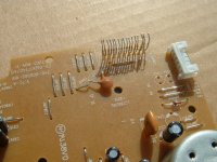
I assuming that the short piece of green ribbon you are using probably provides some level of stray or gimmick capacitance already - have you mounted a crystal directly on the board without some capacitance?
One other question is I noted the thevenin equivalent source impedance of the spdif out with 75//200 is: 55 ohms - are you using 50 ohm coax? I am planning on using 243 and 110 ohm resistors which results in ~75.8 ohm source impedance for my 75 ohm coax. (Of course I do not have 75 ohm bnc..I keep looking...
) I'm assuming signal in the range of 3.3Vpp on the processor chip spdif output.
Sorry to quote this old post, but I calculated the resistors again.
Theoretically it should be 375 and 93.75 Ohm.
(you still woulld have to subtract the chips output impedance from the 375 Ohm)
That would give a perfect 75 Ohm output impedance, 1Vpp unloaded and 0.5Vpp loaded with 75 Ohm.
Any other value will render the coax into an antenna or ignore s/pdif specs. (and thus the receiver input)
--> calculation based on 5Vpp processor spdif ouput.
--> If it's 3.3Vpp, it should be 247.48 and 107.6 Ohm (If this is the case, Kevin's values are the best option!)
Did someone measure the actual chip output?
(would do it myself but the BB has not yet arrived)
BTW: I did not find a translation machine from polish language to english.
Sorry, just google
A question: isn't it a disadvantage, to have a open drive?
No interferences / disturbance from the environment light?
Kind regards
Franz
Franz Gysi said:
No interferences / disturbance from the environment light?
We all listen in a dark room on sundaymorgings only (when the electricity is best for the real audiophile) ;-)))
No, seriously, you might have a point there, but as long as the light is rather constant (and it is most of the times) there will be no audible influence.
I worry most about the dust fallin' in...
Perhaps a useful tip.....
I removed the display-connector but kept the leads. As I just want to use the remote and perhaps the buttons I wanted to get rid of the flat-cable. You can bend the connector upwards (some force) and cut of the sides, then fold the part without leads of the connector forward by sticking a screwdriver into the connector and twist. As the plastic is hard it will break of easily. Now you have a radiator like piece of plastic with the iron leads. Bend the leads up and again with a screwdriver wick out one by one the plastic strips. See picture for result. It should be easy now to add some wires.... if I can find out again what is pin 1...
I removed the display-connector but kept the leads. As I just want to use the remote and perhaps the buttons I wanted to get rid of the flat-cable. You can bend the connector upwards (some force) and cut of the sides, then fold the part without leads of the connector forward by sticking a screwdriver into the connector and twist. As the plastic is hard it will break of easily. Now you have a radiator like piece of plastic with the iron leads. Bend the leads up and again with a screwdriver wick out one by one the plastic strips. See picture for result. It should be easy now to add some wires.... if I can find out again what is pin 1...
Attachments
OneyedK said:
Sorry to quote this old post, but I calculated the resistors again.
Theoretically it should be 375 and 93.75 Ohm.
(you still woulld have to subtract the chips output impedance from the 375 Ohm)
That would give a perfect 75 Ohm output impedance, 1Vpp unloaded and 0.5Vpp loaded with 75 Ohm.
Any other value will render the coax into an antenna or ignore s/pdif specs. (and thus the receiver input)
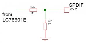
That speaking out in terms of scheme is 375 in series at the output followed with a 93,7 in parallel ........ isnt like that ?
Well I guess that will work realiably if the chip output has enough power ...
Am I going to try a toslink ?
stefanobilliani said:
That speaking out in terms of scheme is 375 in series at the output followed with a 93,7 in parallel ........ isnt like that ?
Well I guess that will work realiably if the chip output has enough power ...
Am I going to try a toslink ?
Yeps, LC78601E uses 5V so at worst case output would still be 4Vpp (If output current is 12mA).
Chip output will have enough power.
/edit: Kevin, your 3.3V-assumption appears to be wrong.
I'll use a 93.1 Ohm as -what you call- the parallel-resistor and an adjustable 500 Ohm as series resistor. Measurement will show the exact value I need for the series resistor.
1Vpp unloaded output, 0.5Vpp loaded output.
Output impedance is more important than exact output voltage, so I won't worry if I end up with 1.2Vpp unloaded and 0.6Vpp loaded with 75 Ohm.
Toslink? In high end? Tsss... ;-)))
Just to avoid confusion .OneyedK said:
Yeps, LC78601E uses 5V so at worst case output would still be 4Vpp (If output current is 12mA).
Chip output will have enough power.
/edit: Kevin, your 3.3V-assumption appears to be wrong.
I'll use a 93.1 Ohm as -what you call- the parallel-resistor and an adjustable 500 Ohm as series resistor. Measurement will show the exact value I need for the series resistor.
1Vpp unloaded output, 0.5Vpp loaded output.
Output impedance is more important than exact output voltage, so I won't worry if I end up with 1.2Vpp unloaded and 0.6Vpp loaded with 75 Ohm.
Attachments
I guess the 12mA in the datasheet (LC78601E) aren't chosen for nothing.
So a recalculation with 12mA and 4Vpp chip output, gives
R1=291 Ohm and R2=100 Ohm to get 1Vpp unloaded and 0.5Vpp loaded with 75 Ohm.
I'll stick with these values. Kevin came prettty close, even starting from the wrong assumption.
So a recalculation with 12mA and 4Vpp chip output, gives
R1=291 Ohm and R2=100 Ohm to get 1Vpp unloaded and 0.5Vpp loaded with 75 Ohm.
I'll stick with these values. Kevin came prettty close, even starting from the wrong assumption.
- Home
- Source & Line
- Digital Source
- Finally, an affordable CD Transport: the Shigaclone story