Erik - looking nice....
 i tried today to cut some real wood - 4mm thick... well, i cut it but it did not stay to long in one piece.... it brakes to easy... i think that i will used some laminated wood for the top metal plate after all... that material wil not brake from looking at it alone....
i tried today to cut some real wood - 4mm thick... well, i cut it but it did not stay to long in one piece.... it brakes to easy... i think that i will used some laminated wood for the top metal plate after all... that material wil not brake from looking at it alone....I use a strong led (looking into it is painfull) and the height is such that it shines exactly in the middle of the cd-edge in a horizontal plane so top and bottom is illuminated.
I also use a standard resistor at 5V so that the led is not dimmed.
IIRC Peter has a link somewhere...he started to experiment with it on a Philips Pro cd-drive.
I also use a standard resistor at 5V so that the led is not dimmed.
IIRC Peter has a link somewhere...he started to experiment with it on a Philips Pro cd-drive.
Zoran said:@sparcle
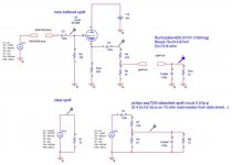
this is more acurate tube spdif if You want,
that one, like most things, from the lampiztor site is not
correct one...
Zoran - thanks for the sch..... have you tried it????? thnx again....
m.massimo said:I removed C952 and changed C916 with a 220u/35 Panasonic FC
I can't say anything about sound at this point, but one thing is sure. The mechanism is less noisy. I don't know why. Mechanism noise was clearly audible, particularly at the beginning of the disc, now it can be barely heard.
m.massimo said:
I can't say anything about sound at this point, but one thing is sure. The mechanism is less noisy. I don't know why. Mechanism noise was clearly audible, particularly at the beginning of the disc, now it can be barely heard.
It is more close to example circuit from datasheet for LA6541. Assume that your inspiration came from there: LM6541 Datasheet
Hallo,
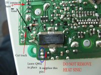
I have chances all the things on the board like the Okapi PDF file and now I will separate the 5 volt power supply from the board and I will feed the Trichord Clock 4 also with a separate power supply, what are the things I need to do now?
I have seen some pictures here on the forum but I can’t find the right pictures anymore.
I found this picture to separate the 5 volt power supply from the board, this is the right one I hope and please let me know that I am right?
Rudy
Attachments
I got a problem
when I power the transport the cd spins clockwise and when the laser try to get the disc It spins constantly in reverse direction showing 00
If I got a puk It almost Immediately spins but not clockwise
also I found that LM7808 Is gone 14 V In 12.9 V out
now I am trying with other stabilizer but nothing new
samoloko said:I got a problem
when I power the transport the cd spins clockwise and when the laser try to get the disc It spins constantly in reverse direction showing 00
If I got a puk It almost Immediately spins but not clockwise
also I found that LM7808 Is gone 14 V In 12.9 V out
now I am trying with other stabilizer but nothing new
It is not clear to me what exactly "...nothing new..." means, but I would check power supply disconnected from transport at each point:
1. mains (AC)
2. trafo sekundar (AC)
3. rectifier diodes
4. New 7808 Vin and Vout (AC and DC)
When everything is correct, connect transport then check 7808 Out again. Check if 7808 getting hot fast. If so, disconnect transport right away.
If still not OK, take a magnifying glass and search for any damage on PCB.
But most of all, you can help yourself trying to remember what you did right before malfunction happened .
samoloko said:I got a problem
when I power the transport the cd spins clockwise and when the laser try to get the disc It spins constantly in reverse direction showing 00
If I got a puk It almost Immediately spins but not clockwise
also I found that LM7808 Is gone 14 V In 12.9 V out
now I am trying with other stabilizer but nothing new
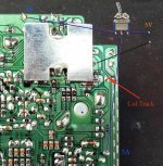
Check the internal supply (from motor controller IC) on the board and make sure it is not fried, should be putting out about 5V, if that is not the case then 12V or more probably got to the digital ICs and they are not really tolerant of voltages much above 6V - hopefully this is not the case, otherwise it is time to look for another boom box. (Been there, done that.)
BMW850 said:I found this picture to separate the 5 volt power supply from the board, this is the right one I hope and please let me know that I am right?
Yes, it looks good. The place to cut is green dot on a track.
Thank you all for the replay.
Now I connect my 2e board and I did exact the same as with my first board.
The board has only the 8 volt power supply for now, I changes that later when the other transformer arrives.
I connect the board to the power supply but the motor will not drive to read the cd, what good be wrong?
Dam I check everything under the loupe 5 times, nothing is wrong no rest solder on the board.
Please tell me it is simple to fix
Rudy
audio1st said:Hello Puffin,
Remove original crystal and connect new clock as below...
I have only just got around to fitting this clock. Audio1st, it is exactly the same as yours. I have connected it as advised (post 1495 page 60) and it is not reading the TOC and no movement at all from the laser or motor.
From the photo you put on of your clock in situ, it would appear that one of the wires (ground?) is not connected at the terminal block?
There is an OUT and a GRD. I have connected the OUT to the pad you marked XO on your diagram and the GRD to the pad next to it (middle pad of crystal)
Any ideas?
audio1st said:Hi, added the cheap ebay clock and the Clearaudio disc clamp and it still works
Sound seems clearer to me, guess thats the clock not the clamp
Original photo here (post 1637 page 66)
Problem solved
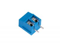
It was a stupid fault from me, I used a print kroonsteen I don’t know the name in English so see the picture.
One pin is connected to the + and the other to the – to the board that is good, bud under need the board I connect the – from the print kroonsteen also to the – that was the problem, no power to the motor
Rudy
Attachments
- Home
- Source & Line
- Digital Source
- Finally, an affordable CD Transport: the Shigaclone story