hello everyone
In case if anyone is interested in modding their Dac-AH's here's a great one for you
I pretty much took the idea from DDDAC1543 by Doede! Thank you D.
It's very simple.
I made a reclocking module with its own power supply and added to my dac-ah.
Improvement? Hell yeah
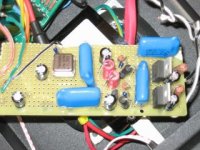
here's a picture of my module.
it's very unorganized but it works like a charm.
In case if anyone is interested in modding their Dac-AH's here's a great one for you
I pretty much took the idea from DDDAC1543 by Doede! Thank you D.
It's very simple.
I made a reclocking module with its own power supply and added to my dac-ah.
Improvement? Hell yeah
here's a picture of my module.
it's very unorganized but it works like a charm.
Attachments
Puffin said:I have a Dac Ah that I modded to passive output. Can you let us that the info to carry out this mod.
hey there,
this is fairly easy except for cs8414 part
I do have this with bypass mod. the reclock works great with any mods as it removes jitters by alot (more info at www.dddac.de)
step by step method
1.www.dddac.de download the schematics AND the PCB prints(make things very easy) (Thanks D) (one pdf file)
2.Look for the schematics of 5V power supply for both Tentlab XO clock and the counter 74VHC..(they are the same)
(Since you by passed the opamps, you can actually mod the power supplies for opamps so it outputs +5V.) I didnt do this as i didnt know how to create a clean supply so i just followed doede's)
3.make two identical power supplies and Tentclock part and the counter part on one jumper board in the same layout as that of doede's (since my jumper board didnt have the ground, I connected all the ground points and connected to one of the ground points on main Dac-ah.
4.after your done with your board you should have 4 wires hanging out for/from
I. Original power supply (I connected to the +15V supply before the opamp)
II. Ground (I connected it to the ground next to +15V)
III.FS wire from 74VHC - this goes to FS pin of CS8414 (hard to solder.. get surface mount solder or use needle thin soldering iron)
IV.Sck wire from 74 VHC -this goes to Sck pin of CS8414(same as above)
5.Your CS8414 is prolly outputing FS and Sck right now so we have to change the mode of CS8414 by supplying high to pin M0. this will make your CS8414's FS and Sck pins as inputs. This is the trickiest part...
First you need to disconnect this pin from grounded. so go ahead and suck all the lead out of this pin... what you need to do is lift this pin so that its not touching grounded... the easiest way to lift is actually to push it to either side, make sure that you dont break the pin off... once the pin is lifted and detached from the ground, using just little amount of lead, solder the pin to the one next to it, since that one is supplied high (either side is fine, they both are supplied high)
(Remove capacitors and other components around the CS8414 before doing any of these small soldering and lifting because they really get in the way)
**ALWAYS USE MULTIMETER TO CHECK THE CONNECTIVITY AND ALSO CHECK THE VOLTAGE SUPPLY BEFORE TURNING IT ON**
any questions, just leave a reply
- Status
- This old topic is closed. If you want to reopen this topic, contact a moderator using the "Report Post" button.