Hi All,
I have finally managed to build a discrete IV stage for my TDA1541A based DAC.
I've only just got it working, with my 'experimenting' PSU (only regulated with 7815/7915) and have only listened to it briefly through headphones.
However, on first impressions it sounds alright actually. I think there is a lot of detail so far. I am looking forward to feeding it from my DAC PSU, which is regulated with lm3x7, and then TL431. Then I'll be able to compare it to my humble LM6172.
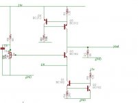
The circuit is a duplicate of the one posted (obviously for stereo), but the voltage bias (generated by the 20k trimmer) is shared by both channels. I assume this is good practice, as it sets the gain for both stages. Or should I have two biases? One per channel?
Adjusting the bias is subtle, and at extremes causes distortion, so I suspect I will need to adjust it using a test CD and oscilloscope to ensure distortion is reduced/eliminated as best as possible.
I am also hoping to get this running on a split supply, rather than 0-15v, as the DC offset is quite large.
Also, I suspect I will follow it with a current sourced CFP based emitter follower, and I'll add a voltage offset to reduce the DC offset to zero.
Cheers,
Phil
I have finally managed to build a discrete IV stage for my TDA1541A based DAC.
I've only just got it working, with my 'experimenting' PSU (only regulated with 7815/7915) and have only listened to it briefly through headphones.
However, on first impressions it sounds alright actually. I think there is a lot of detail so far. I am looking forward to feeding it from my DAC PSU, which is regulated with lm3x7, and then TL431. Then I'll be able to compare it to my humble LM6172.
The circuit is a duplicate of the one posted (obviously for stereo), but the voltage bias (generated by the 20k trimmer) is shared by both channels. I assume this is good practice, as it sets the gain for both stages. Or should I have two biases? One per channel?
Adjusting the bias is subtle, and at extremes causes distortion, so I suspect I will need to adjust it using a test CD and oscilloscope to ensure distortion is reduced/eliminated as best as possible.
I am also hoping to get this running on a split supply, rather than 0-15v, as the DC offset is quite large.
Also, I suspect I will follow it with a current sourced CFP based emitter follower, and I'll add a voltage offset to reduce the DC offset to zero.
Cheers,
Phil
Attachments
Had another listen this morning.
It does sound slightly brighter than my opamp stage (from memory), but I do suspect some of that might be down to having only heard this through my Grados (which are a little bright in nature compared to my speakers).
There does seem to be lots of detail, and I do get the impression that its unlikely to be fatiguing.
I think there is a lot of potential for this stage when it is running off my DAC PSU.
Tonight I'll check the bias and thus output with my scope and have a proper listen on my LS3s tonight.
I'm just really gutted I have only MP3s on a PC and cheapish headphones at work.
But overall, very pleased
Thank goodness, some feedback. I need it!
Ipanema,
This is my first adventure into discrete IV (as you'll discover as you read the rest of this post ), so alas I haven't compared to the Pass D1.
Pars,
Is the 6k resistor the IV resistor? I thought it was used to provide a voltage bias for the common base amplifier - although I'd be lying if I said that I completely understood this circuit.
I use this bias for both IV converters (left and right) and I still have a stereo image, so I suspect this isn't an IV resistor.
I do suspect 6k is a bit high though...
Last night I connected it up to an oscilloscope and noticed that the lower half of a full scale sine wave could be distorted (smaller in magnitude than the upper half) if not very carefully adjusted. I suspect this is due to the amount of current into the base - which led me to my first (probably of many) mistake. I think the potentiometer should be a variable resistor, which could then be tweaked to allow more current into the base. Since then, I've noticed that is what is done in other IV converters. I'll change that and see what happens.
I finally managed to listen last night and I was amazed by how it sounded. I can't say if its better (I suspect it is), but its sounds totally different to my old opamp IV converter. Its typical to expect incremental improvements when changing things, but this sounds completely different. Almost like Monty Python.
Perhaps its because its open loop, perhaps its because its class A, or both.
It must be an improvement, because there are lots of things I've never heard before I am now hearing.
I do like it, just need to get used to it.
Anyway, I need to change the bias circuit. I agree 6k might be too high (although I did see one circuit with 100k and a 20k variable resistor!), and I need to make the pot a variable resistor to increase current.
Also, I need to find a definitive text on common base amplifiers. Horowitz and Hill on briefly touch on the subject. None of my other electronics books really discuss it. I've found a few articles on the web (wikipedia has a reasonable description). I suppose I haven't found anything quite applicable to how it works as an IV converter.
That's why I decided to build one and learn through investigation.
All I currently (forgive the pun) think I know is that its essentially a voltage amplifier with a very low input impedance, which the DAC likes (as its a current sink), and the gain is set by the voltage bias (although it would make more sense to me if it was a current bias) into the base.
If anyone has the correct description, or a link to it, I'd be very grateful.
Ipanema,
This is my first adventure into discrete IV (as you'll discover as you read the rest of this post
), so alas I haven't compared to the Pass D1.Pars,
Is the 6k resistor the IV resistor? I thought it was used to provide a voltage bias for the common base amplifier - although I'd be lying if I said that I completely understood this circuit.
I use this bias for both IV converters (left and right) and I still have a stereo image, so I suspect this isn't an IV resistor.
I do suspect 6k is a bit high though...
Last night I connected it up to an oscilloscope and noticed that the lower half of a full scale sine wave could be distorted (smaller in magnitude than the upper half) if not very carefully adjusted. I suspect this is due to the amount of current into the base - which led me to my first (probably of many) mistake. I think the potentiometer should be a variable resistor, which could then be tweaked to allow more current into the base. Since then, I've noticed that is what is done in other IV converters. I'll change that and see what happens.
I finally managed to listen last night and I was amazed by how it sounded. I can't say if its better (I suspect it is), but its sounds totally different to my old opamp IV converter. Its typical to expect incremental improvements when changing things, but this sounds completely different. Almost like Monty Python.
Perhaps its because its open loop, perhaps its because its class A, or both.
It must be an improvement, because there are lots of things I've never heard before I am now hearing.
I do like it, just need to get used to it.
Anyway, I need to change the bias circuit. I agree 6k might be too high (although I did see one circuit with 100k and a 20k variable resistor!), and I need to make the pot a variable resistor to increase current.
Also, I need to find a definitive text on common base amplifiers. Horowitz and Hill on briefly touch on the subject. None of my other electronics books really discuss it. I've found a few articles on the web (wikipedia has a reasonable description). I suppose I haven't found anything quite applicable to how it works as an IV converter.
That's why I decided to build one and learn through investigation.
All I currently (forgive the pun) think I know is that its essentially a voltage amplifier with a very low input impedance, which the DAC likes (as its a current sink), and the gain is set by the voltage bias (although it would make more sense to me if it was a current bias) into the base.
If anyone has the correct description, or a link to it, I'd be very grateful.
I guess this is the best I've seen so far. Must sit down and read it properly...
http://users.ece.gatech.edu/~mleach/ece3050/notes/bjt/cbamp.pdf
http://users.ece.gatech.edu/~mleach/ece3050/notes/bjt/cbamp.pdf
There is a thread on similar circuits and I've posted there my schematics from 1994:
http://www.diyaudio.com/forums/showthread.php?postid=229203#post229203
As you may see it looks very similar to yours and indeed it sounded very nice. However I've incorporated some LP filtering - perhaps it may help to cure the brightness you're experiencing.
Cheers
Alex
http://www.diyaudio.com/forums/showthread.php?postid=229203#post229203
As you may see it looks very similar to yours and indeed it sounded very nice. However I've incorporated some LP filtering - perhaps it may help to cure the brightness you're experiencing.
Cheers
Alex
Hi Alex,
Thanks for the link. Hopefully it will be useful reading.
What kind of regulation did you use for your IV converter? With the low PSRR of these kinds of circuit, I'm interested on what others have settled for.
I really want to improve my understanding of this circuit so I can understand how component changes affect the system.
I do actually have a 3rd order passive filter after this stage as the DAC is 4x oversampling.
I think it initially sounded a bit bright because I hadn't adjusted the bias with an oscilloscope to minimise distortion, and I was listening using my Grados - which tend to be a bit bright (I tend to listen to new DIY kit with rubbish sony headphones first, then the Grados, then the amp and speakers - just in case something gets fried).
Listening through my LS3/5As, the harshness is gone thankfully.
I think at the moment my bias circuit is incorrect (I reckon its limiting the current into the base) and hopefully fixing that'll help a lot.
Cheers,
Phil
philpoole said:[snip]Pars,
Is the 6k resistor the IV resistor? I thought it was used to provide a voltage bias for the common base amplifier - although I'd be lying if I said that I completely understood this circuit.
I use this bias for both IV converters (left and right) and I still have a stereo image, so I suspect this isn't an IV resistor.
I do suspect 6k is a bit high though...[snip]
I think he means R3, not R6...
Jan Didden
philpoole said:What kind of regulation did you use for your IV converter? With the low PSRR of these kinds of circuit, I'm interested on what others have settled for.
I've used at the time just a plain stabilsed supply on LM317.
philpoole said:I think at the moment my bias circuit is incorrect (I reckon its limiting the current into the base) and hopefully fixing that'll help a lot.
To start with you may try adding another 10-22 uF capacitor between the ground and the base of Q3. At the moment the base is looking into the pot and can see up to 5K there. It will transfer directly into 25-50 additional Ohms of the input impedance.
Cheers
Alex
LOL! Of course. I am feeling particularly dumb now.
I was recently thinking how it was using that to convert to a voltage as well!
The schematic I knocked up is a record of the circuit I built, not exactly a design. As you can guess, I have an abundance of 6k resistors, BC182s and BC212s! They seemed reasonable values at the time.
That makes sense, and is something I else can change. My op amp I/V uses 1.8k, so again it does seem a bit high.
Thanks everyone for steering me towards the right thought processes. Its much appreciated!
To start with you may try adding another 10-22 uF capacitor between the ground and the base of Q3. At the moment the base is looking into the pot and can see up to 5K there. It will transfer directly into 25-50 additional Ohms of the input impedance.
Sounds like a plan. I've found an equation for the input impedance of a common base amplifier and am keen to work out how to reduce that.
Cool. Thanks for the advice.
janneman said:
I think he means R3, not R6...
Jan Didden
Yes, sorry, R3 was the one I was looking at... didn't spot the other 6k resistor.

Hi philpoole,
The 20 k potmeter is to set zero volt at the input (within +/- 25 mV) so that the DAC will be happy. It is not gain setting, the gain is determined by the ratio of 6 kohm to 120 ohm. 1 mA on the input results in 0.12 V on the 120 ohm resistor, which will be amplified by 50 x, so you get 6 V peak for 1 mA. The TDA1541A gives 2 mA full scale, so you will get 12 V peak or about 8.5 V RMS. If this is too large, reduce the 6 kohm to, say 1.5 kohm.
In the opamp I/V the 1.8 kohm determines the transconductance, not the gain. The input impedance is actually much lower, in the order of milliohms.
I like your design. Just make sure it does not drift with temperature (I mean the input 0.00 mV DC voltage loaded with the DAC chip).
Laszlo
Hi Lazlo,
Thanks for the kind and useful words.
design! LOL! I basically found a very basic common base amplifier and replaced the collector and emitter resistors with current sources as a starting block. There really wasn't any design involved (as you can tell from the use of a pot instead of a variable resistor).
In a lot of respects, the opamp solution does seem more ideal - especially wrt to pleasing the DAC's criteria. However, I am impressed by how this sounds - probably because its class A and there's no feedback.
From everyone's words here, I do suspect my large load (I/V) resistor is a tad high. It might explain the subtle clipping I've been seeing with large signals if not correctly calibrated.
Another night of tinkering awaits!
Cheers,
Phil
Jocko's IV
Philpoole, It's essentially Jocko's simple IV-converter back in 2002.
http://www.diyaudio.com/forums/showthread.php?s=&threadid=6121&highlight=
Philpoole, It's essentially Jocko's simple IV-converter back in 2002.
http://www.diyaudio.com/forums/showthread.php?s=&threadid=6121&highlight=
Hi Qserra_Tico_Tico,
Well, before embarking on this, I did notice thats everal IV converters were essentially common base (or common gate) amplifiers (including Jocko's).
I did consider doing his desiign, but I was unsure about using a current mirror for setting the bias (alhough I am now considering it), and I preferred using this type of constant current source.
Both design decisions were made on using techniques I am more familiar with, in order to help understand the whole circuit.
I reduced the load resistor to about 1.6k, added 100uF between the base and ground, and turned the pot into a variable resistance, and it sounds lovely. Its much easier to adjust now to reduce distortion. I think its an amazing improvement over the opamp IV. I don't think I could turn back.
However, it does seem sensitive to interference - probably due to its low PSRR and that its currently laid out all over the floor (until I mount it properly in its enclosure).
Janneman, I shall look into servos for this. It might be a good idea. Although, the DC offset is quite small now, and I'm hoping to eventually have a balanced output with two DACs.
Cheers,
Phil
Phil,philpoole said:From everyone's words here, I do suspect my large load (I/V) resistor is a tad high. It might explain the subtle clipping I've been seeing with large signals if not correctly calibrated.
You don't have any "physical" I/V resistor here. It is formed by the input impedance of the common base transistor. It is given as the common base h11 parameter which can be derived from the catalogue common emmitter h parameters. I don't know the formula by heart, but I can look after it if you are interested. The goal is to keep it below 5... 10 ohms. If it is higher, you get clipping -> distortion at signal peaks.
Another reason of the clipping could be that you have some DC voltage at the input. You can safely measure it in-situ with a CD millivoltmeter. The goal here again is to keep it below a few millivolts. The servo that janneman proposed is a good idea, but if the circuit does not drift, it might not be necessary.
Laszlo
Hi Laszlo,
I should have written 'large load (I/V?)' because I agree its not the IV resistor as you'd expect in a passive sense, but others had called it that.
I know it works differently to passive versions in the sense that it is basically providing a tiny input resistance for the current output of the DAC, and then applying voltage gain - as opposed to providing a smallish resistance to convert a current into a voltage - which is less desirable for a DAC.
As far as I can tell, finely adjusting the trimmer seems to be enough to ensure the clipping is avoided. However, I haven't been able to run it for a long enough time to discover if there is a problem with drifting.
I'm also starting to think that this could really do with a buffer on its output. I don't really like a section of a system having to do more than one task - if I can help it, but I think that's for another time.
From what remember in my (distant) previous life as a student, isn't h11 basically re (the internal resistance - as opposed to Re)?
Cheers,
Phil
- Status
- This old topic is closed. If you want to reopen this topic, contact a moderator using the "Report Post" button.
- Home
- Source & Line
- Digital Source
- Oh no! Not another discrete IV converter