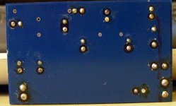
Here's a pic showing the trace and circuit layout as best as I can manage:
[URL=http://img151.imageshack.us/my...geshack.us/img151/941/sc2id0.th.jpg[/IMGDEAD][/URL]
Lee.
[URL=http://img151.imageshack.us/my...geshack.us/img151/941/sc2id0.th.jpg[/IMGDEAD][/URL]
Lee.
And another showing some component values:
I will measure any components I can.
The aim is to try and separate the digital and analogue supplies and feed them from external low-noise regs.
Cheers,
Lee.
An externally hosted image should be here but it was not working when we last tested it.
I will measure any components I can.
The aim is to try and separate the digital and analogue supplies and feed them from external low-noise regs.
Cheers,
Lee.
First of all you need to look at what chips etcv are on the pcb
LM336-2.5 is a 2.5V ref diode (actually a ic but shown on a cct as a diode, very low noise)
TL084 is a quad opamp and very good for noise rejection on voltage rails
I can also see the freq ref cap is missing (smt)
Brent
LM336-2.5 is a 2.5V ref diode (actually a ic but shown on a cct as a diode, very low noise)
TL084 is a quad opamp and very good for noise rejection on voltage rails
I can also see the freq ref cap is missing (smt)
Brent
So basically the clock two chips with its caps and res form a low noise regulator which feed the whole pcb.
Maybe the quad opamp chip actually feeds two or more rails out of it with the one 2.5v ref.
Its actually pretty good but the only suprise for me is no drive transistor, I know the clock 3 has a drive transistor on the pcb
Brent
Maybe the quad opamp chip actually feeds two or more rails out of it with the one 2.5v ref.
Its actually pretty good but the only suprise for me is no drive transistor, I know the clock 3 has a drive transistor on the pcb
Brent
Bloomin' eck. you don't hang about! I was still looking for datasheets etc to look at.
I have two of these btw.
Would it be worth adding that smt cap? Also, where there's a wire link on this one behind the xtal, there's a cap on the other clock.
I'll hook it up to a power supply and have a poke around with the dmm.
Cheers,
Lee.
I have two of these btw.
Would it be worth adding that smt cap? Also, where there's a wire link on this one behind the xtal, there's a cap on the other clock.
I'll hook it up to a power supply and have a poke around with the dmm.
Cheers,
Lee.
The reg is tx, Schottky's, 10,000uF 63v BHC Aerovox Alt, lm317 with 4x10v zeners for lower noise, 3300uF 16v bc Comp, and 100uF BG FK between Vin and Gnd directly on clock pins. All that and it's not that good!
Any idea on the value of that cap, looking at the other clock that's in the player, it doesn't have it either. Is it the 12pf one?
Lee.
Any idea on the value of that cap, looking at the other clock that's in the player, it doesn't have it either. Is it the 12pf one?
Lee.
Cheers for the help mate. I've removed the clock from my player and looking at the back it seems that I may have damaged one of the traces!
I have now put the other clock in the player and it sounds loads better.
I will whip out that 3300uF cap from the psu.
When I next order from Farnell I think I'll get a couple of the ADtl084 chips. The datasheet says it's an improved version of tl084 with better ps rejection and a faster slew rate etc. Maybe worth a go.
Are you sure that cap is 18pf, it's for the dac (16.934 mhz)not servo.
Cheers, Lee.
Attachments
- Status
- This old topic is closed. If you want to reopen this topic, contact a moderator using the "Report Post" button.
- Home
- Source & Line
- Digital Source
- Modifying Superclock II