Hi Folk!
I've a question for clock's masters.
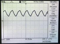
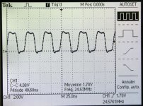
I've a TCXO with an output of 1.71v. I want to connect it to a device to replace a regular cristal. I've enclosed the scope signal if this can help.
What is the right resistor value to insert to have the right output voltage? In fact, I don't know what should be the right voltage.
Unfortunaly, I don't have the device schematic but the first chip in in the circuit is an HCU04.
Stephane
I've a question for clock's masters.
I've a TCXO with an output of 1.71v. I want to connect it to a device to replace a regular cristal. I've enclosed the scope signal if this can help.
What is the right resistor value to insert to have the right output voltage? In fact, I don't know what should be the right voltage.
Unfortunaly, I don't have the device schematic but the first chip in in the circuit is an HCU04.
Stephane
Attachments
hello,
I am playing around with my VRDS-10 and moving onto mod the clock part. Can you do me a favour that forward the schematic to my mail box 8888po@gmail.com Merci!
I am playing around with my VRDS-10 and moving onto mod the clock part. Can you do me a favour that forward the schematic to my mail box 8888po@gmail.com Merci!
mkliu said:hello,
I am playing around with my VRDS-10 and moving onto mod the clock part. Can you do me a favour that forward the schematic to my mail box 8888po@gmail.com Merci!
I've to look in my archives.
stef1777 said:
I've to look in my archives.
Great Thanks and very much appeciated your help!
yygomez said:Hi Stephane,
Remove C69, C60, and Q3. feed the output of your TCXO to pin1 trough a 0,01uf cap capacitor. That should do it.
please note tha you have to keep the bias resistor r48 ( do not remove).
Jorge
Curently, I've connected the TCXO using an 47R resistor and it work. What is the advantage to use an smal caps instead?
mkliu, I'v sent the files.
.
stef1777 said:
Curently, I've connected the TCXO using an 47R resistor and it work. What is the advantage to use an smal caps instead?
mkliu, I'v sent the files.
.
Got the file, it's very useful.....I just start putign a new TXCO in my vrds10.....
yygomez said:in short answer, Your TCXO is 3.3v, the circuit is 5v. With the cap and the R48 1M biasing the 74HCU04 the circuit is going to trigger on the steepest part of the TCXO waveform which means less jitter.
Thanks JG!
I've put a 10nF SMD COG in place of the 47R. Still working. Tried to look for a sound difference without success. ;-)
Could you please explain a little more your advice? It seems to be a relation between Vih and Vil, or Voh and Vol and Vcc of the SN74HCU04?
- Status
- This old topic is closed. If you want to reopen this topic, contact a moderator using the "Report Post" button.
- Home
- Source & Line
- Digital Source
- Right voltage output using TCXO