")
I have the AD1955 eval kit, and AD has a series of ferrite beads in the schematic between analog and digital grounds, but all the connections are left open. Just looking over the schematics, the psu ground is connected to the analog supply. It appears that the digital ground is floating, or perhaps the AD1955 is providing the digital ground reference. The AD1955 appears to be the only component that connected to both grounds.
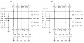
AGND1&2 are tied together to analog ground and DGND is connected to digital ground. This is the only reference I could find connecting the two ground planes together.
When I get more time tomorrow I'll look more carefully and let you know what I find.
-David
AGND1&2 are tied together to analog ground and DGND is connected to digital ground. This is the only reference I could find connecting the two ground planes together.
When I get more time tomorrow I'll look more carefully and let you know what I find.
-David
banana said:For the ferrite beam between AGnd and DGnd... datasheet suggest to use it, but be open minded to try a direct short.
If you have a Spectrum Analyzer, watch for radiation of MCLK.
Yes, the AD1955 eval board also uses one ferrite bead to connect the DGnd to AGnd just underneath the AD1955 chip on the bottom side of the board. Only the Agnd to directly connected to the PSU common ground.
-David
- Status
- This old topic is closed. If you want to reopen this topic, contact a moderator using the "Report Post" button.