I am waiting for a kit to arrive from fellow member John Dozier. It will come with the CD Pro module.
I have got the circuit diagram, but it does not have the component values, so if anyone has a component list I would be very grateful.
If anyone would like a copy of the circuit diagram, send me your Email address and I will send it over.
Cheerz, Alex.
I have got the circuit diagram, but it does not have the component values, so if anyone has a component list I would be very grateful.
If anyone would like a copy of the circuit diagram, send me your Email address and I will send it over.
Cheerz, Alex.
Transport kit arrived, so was able to start soldering over the weekend. All the main boards have been soldered so will start building the case and do the mains wiring.
Overall it is a well put together kit, but is for the more experienced builders due to lack of a build manual.
Overall it is a well put together kit, but is for the more experienced builders due to lack of a build manual.
transformer's connections.
Hello,
I don't post a lot") , and I'm not a specialist in electronic.
, and I'm not a specialist in electronic.
I have bought an HIFIDIY mini Cd-pro2 kit and a CD-Pro2 LF. Everything is soldered now, except the digital output connectors.
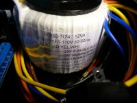
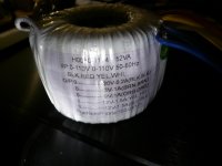
Can someone help me to connect the transformer wires (wich color in which hole on the pcb ?) ? I have the white transfo, not the Plitron's one.
I don't want to make a mistake, as I don't have knowledges and tools to test a transfo.
Thanks in advance.
Hello,
I don't post a lot
, and I'm not a specialist in electronic.I have bought an HIFIDIY mini Cd-pro2 kit and a CD-Pro2 LF. Everything is soldered now, except the digital output connectors.
Can someone help me to connect the transformer wires (wich color in which hole on the pcb ?) ? I have the white transfo, not the Plitron's one.
I don't want to make a mistake, as I don't have knowledges and tools to test a transfo.
Thanks in advance.
Attachments
Hello,
I don't post a lot
I have bought an HIFIDIY mini Cd-pro2 kit and a CD-Pro2 LF. Everything is soldered now, except the digital output connectors.
Can someone help me to connect the transformer wires (wich color in which hole on the pcb ?) ? I have the white transfo, not the Plitron's one.
I don't want to make a mistake, as I don't have knowledges and tools to test a transfo.
Thanks in advance.
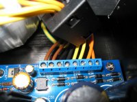
If you can send me a photo of the transformer lead out wires and the white label showing the voltages available with a top view of the main board where the connector blocks are, I will show you where they all go.
The kit is very good when finished, well worth the time spent on it.
All the best,
Alex.
Hello Alex,
Thanks a lot for your help.
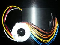
You can find the photos below. I have put a number on each input on the connector block. So you can, as you mentionned, tell me which color in which hole.
For the AC wires, I have the same question, but it seems there are photos on hifidiy.net site. I will examine them carrefully to understand how to connect the AC wires on the IEC connector and on the button of power on/off.
Is it possible to you to tell me which holes for the 9V and which ones for the 5V ?
I'm sure it will sound great, compare to my consonance cd120 used as a transport. I will try later to upgrade the transport (transformer outside, better regulators ?).
Thanks again Alex.
Jean-Louis.
Thanks a lot for your help.
You can find the photos below. I have put a number on each input on the connector block. So you can, as you mentionned, tell me which color in which hole.
For the AC wires, I have the same question, but it seems there are photos on hifidiy.net site. I will examine them carrefully to understand how to connect the AC wires on the IEC connector and on the button of power on/off.
Is it possible to you to tell me which holes for the 9V and which ones for the 5V ?
I'm sure it will sound great, compare to my consonance cd120 used as a transport. I will try later to upgrade the transport (transformer outside, better regulators ?).
Thanks again Alex.
Jean-Louis.
Attachments
Hello Djilbe,
I have also build this transport and i'm still very happy with it. You're gonna love it!
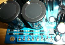
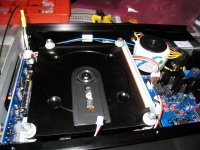
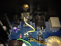
See the photo for the connections. You don't need the blue wires.
I do not have a very clear picture of the mains wiring. Connect the blue and red wires to each other and the remaining two wires are connected to the power inlet. For a larges picture click here.
I have also build this transport and i'm still very happy with it. You're gonna love it!
See the photo for the connections. You don't need the blue wires.
I do not have a very clear picture of the mains wiring. Connect the blue and red wires to each other and the remaining two wires are connected to the power inlet. For a larges picture click here.
Attachments
Last edited:
Hello,
It's me again.
I just want to understand one or two things.
On the nlue connector block, there are 4 couples of wire. But I see 3 rectifiers bridges on the pcb. Can someone explain to me where the brown couple on Corpius photo go ? As it seems to me that the yellow and the orange couples go to the MUR160, and the black couple goes to the integrated bridge.
Is it possible to know too which voltage each couple must give ? The 5V, another 5V, the 9V and a 12V come from where ?
Thanks in advance an sorry for all those non specialist questions.
In my (admittedly limited) experience nothing comes close to this transport coupled with a Hagerman Chime DAC. The presentation is extremely neutral (kind of an oxymoron, I suppose, but I can't think of anything better), and only loses out to SACD in my system because it's not surround sound - in two channel it's indistinguishable or even a little better. I have never heard a commercial high end ($1000+) player though.
I totally agree with schubert on the neutral presentation. It has a large soundstage and it is very revealing. it can easily compete with commercial players that are costs triple the amount these player costs.
However there are some parts that can be updated for even better performance, fi the voltage regulators or the capacitors. However even with the standard supplied components it is already very good.
However there are some parts that can be updated for even better performance, fi the voltage regulators or the capacitors. However even with the standard supplied components it is already very good.
Hello,
I'm interested in upgrading the voltage regulators.
I have already upgraded the capacitors.
I'm about to put two more 5V and 9V transformers in an external chassis with the supplied one.
Now I'm looking for informations to upgrade the clock (if benefic) and the regulators.
So don't hesitate to give informations to us.
Thanks in advance.
I am having same problem...need help !!
Hi Cal,
I am having similar problem as yours. Have you managed to solve it? I need help as I have been trying to t/shoot still unable to resolve. I have asked Candy, not much help.
May be you can help?
Thank you.
I have a little problem with Big CDpro....
Everyting fine, check the cdpro supply 9and 5 volt.
Display seems working fine.
14.3 and 5 volt display are find.
But the motor is not spin/any movement at all.
The optic seems moving fine.
The display says loading ... Please wait ... And wait...
So ... It is not spinning at all.
Does anyone has this probelm before?
Cal
Hi Cal,
I am having similar problem as yours. Have you managed to solve it? I need help as I have been trying to t/shoot still unable to resolve. I have asked Candy, not much help.
May be you can help?
Thank you.
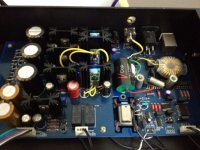
Big CDPro2 upgrade
I have been playing with this for 3 to 4 years now since I am the first batch of buyer. There are certainly some hardship as being the first batch of user but eventually its fun.
These are the upgrades I made in the course of my modification in order of; in my humble opinion, significance: -
Independent regulator for the crystal
The clock is always an important component in a CD drive because it delivers the correct timing. I started to supply the clock with an independent 7805 and found noticible improvement that this small amount of money can buy. It provides a clear backgrounde and more details than before. I also tried to put indivdual regulator to the logic ics but none of them have such improvement by providing an independent regulator to the crystal. Eventually, I purchased a DEXA regulator for the crystal and the improvement goes to an even higher level.
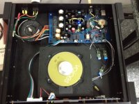
Plitron transformer
I can never imagine that a transformer can bring such improvement to a CD transport. In my mind, a CD transport delivers 0 and 1 from the disc therefore the transformer should never be in the picture of quality but I am totally wrong.
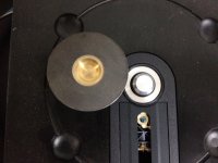
Spindle and disc clamp upgrade
I found on taobao a metal disc clamp with brass center and metal spindle to replace the magnetic disc weight and plastic spindle of the CDPro2 and it delivers audiable improvement, especially in the bass sections. However, I can't find it anymore.
75ohmes conneting cable from partsconnexion
This tiny yellow coaxiel cable makes a different although it is only a few cm. Try it and you would not regret.
5V DEXA regulator for CDPros2
This produce a darker background again. I wonder would there be any improvement if I change the 3.3V regulator at the bottom of the drive to DEXA or the latest version of Belleson SPM 3.3V regulator.
Changing the rectifier to BYV27-200
My friends said the sound becomes more musical but actually I can't tell.
Other not-so-significant improvement I've been made
DEXA 9V for the drive motor
Changing the output capacitor to V-Cap
Changing the coupling transformer to Audionote silver transformer
Changing the transistors to Caddock MK series, RPR etc.
Changing the power capacitors to Blackgate non-polar
Changing the wires to Oyaide internal connecting wire
Changing to oscon and tantalum caps
In my wish-list
I once contacted the owner of hifidiy.net and talked about my experience to improving the big CDPro2. He gave me the contact of the original designer of the PCB for further discussion. However, the discussion was not continued because I am the only one who opt for the change and the cost would be too high just to make one for myself. With the latest debut of ADM1750, I am thinking if anyone would be interested to opt for the development of a new board using this regulator because this is a much cheaper version than DEXA or Belleson.
I have been playing with this for 3 to 4 years now since I am the first batch of buyer. There are certainly some hardship as being the first batch of user but eventually its fun.
These are the upgrades I made in the course of my modification in order of; in my humble opinion, significance: -
Independent regulator for the crystal
The clock is always an important component in a CD drive because it delivers the correct timing. I started to supply the clock with an independent 7805 and found noticible improvement that this small amount of money can buy. It provides a clear backgrounde and more details than before. I also tried to put indivdual regulator to the logic ics but none of them have such improvement by providing an independent regulator to the crystal. Eventually, I purchased a DEXA regulator for the crystal and the improvement goes to an even higher level.
Plitron transformer
I can never imagine that a transformer can bring such improvement to a CD transport. In my mind, a CD transport delivers 0 and 1 from the disc therefore the transformer should never be in the picture of quality but I am totally wrong.
Spindle and disc clamp upgrade
I found on taobao a metal disc clamp with brass center and metal spindle to replace the magnetic disc weight and plastic spindle of the CDPro2 and it delivers audiable improvement, especially in the bass sections. However, I can't find it anymore.
75ohmes conneting cable from partsconnexion
This tiny yellow coaxiel cable makes a different although it is only a few cm. Try it and you would not regret.
5V DEXA regulator for CDPros2
This produce a darker background again. I wonder would there be any improvement if I change the 3.3V regulator at the bottom of the drive to DEXA or the latest version of Belleson SPM 3.3V regulator.
Changing the rectifier to BYV27-200
My friends said the sound becomes more musical but actually I can't tell.
Other not-so-significant improvement I've been made
DEXA 9V for the drive motor
Changing the output capacitor to V-Cap
Changing the coupling transformer to Audionote silver transformer
Changing the transistors to Caddock MK series, RPR etc.
Changing the power capacitors to Blackgate non-polar
Changing the wires to Oyaide internal connecting wire
Changing to oscon and tantalum caps
In my wish-list
I once contacted the owner of hifidiy.net and talked about my experience to improving the big CDPro2. He gave me the contact of the original designer of the PCB for further discussion. However, the discussion was not continued because I am the only one who opt for the change and the cost would be too high just to make one for myself. With the latest debut of ADM1750, I am thinking if anyone would be interested to opt for the development of a new board using this regulator because this is a much cheaper version than DEXA or Belleson.
Attachments
Last edited:
Hello Djilbe,
I have also build this transport and i'm still very happy with it. You're gonna love it!
See the photo for the connections. You don't need the blue wires.
I do not have a very clear picture of the mains wiring. Connect the blue and red wires to each other and the remaining two wires are connected to the power inlet. For a larges picture click here.
Started to assemble CDPro2 Mini kit. Tell me please, dear Corpius, when you write that must be connected together red and blue wires, you mean red and yellow?
I have a question, i did built the cdm12 kit (not the cdpro but the one with the plastic laser mechanism) and i do not get a NOS i2S signal at the output of the laser board. Does anybody know the right key combination to set the output to NOS? (now it is Oversampling that's why my TDA1543 emits no sound...
help would be greatly appreciated
help would be greatly appreciated
Does anyone know of a replacement display suitable for my rather dim oled display on my mini cd2 pro
Thanks, Alex.
Hi,
Does someone has an answer for Alex's question ?
Alex himself perhaps ?
Thanks in advance for a reply.
JL
- Status
- This old topic is closed. If you want to reopen this topic, contact a moderator using the "Report Post" button.
- Home
- Source & Line
- Digital Source
- HIFIDIY CD Transport Kit