I put LM6172 (remove OP275) in the I/V converter section and OPA2132P in summing section. I remove DCservo, I have only 5mV DC offset at the OPA2132P output. I remove all sections after OPA2132P.  The sound ? stunning ! Another very important thing. Change the 47uF/85degree Samwha with Sanyo OS-CON SP or SH series in the digital section, near clock, C55 and C49 ..... In the I/V section I remove C33, C34.........in the summing section I remove C22 and C27 and I moved the negative feedback of the OPA2132 at the output (I remove discrete section and other filters).
The sound ? stunning ! Another very important thing. Change the 47uF/85degree Samwha with Sanyo OS-CON SP or SH series in the digital section, near clock, C55 and C49 ..... In the I/V section I remove C33, C34.........in the summing section I remove C22 and C27 and I moved the negative feedback of the OPA2132 at the output (I remove discrete section and other filters).greierasul said:I put LM6172 (remove OP275) in the I/V converter section and OPA2132P in summing section. I remove DCservo, I have only 5mV DC offset at the OPA2132P output. I remove all sections after OPA2132P.
OPA2132???? you mean OPA2134 I hope, I found the C55 it's an obvious one, but where is C49 can't find it anywhere on my circuit diagrams around the Xtal like you said?
I also belive this is going to be a killer dac just hope the transports up to it as well, after a clock upgrade?
Cheers George
greierasul said:NOOOOO, I put OPA2132P (so, P !).
Oh yes of course I forgot you removed the dc servo and now using a single insted of the double.
I still think if you use a AD825 in place of the OPA2132 as the output amp it will sound even better as I have compared the AD825 and OPA213X, and the AD825 has soooo much more slam and dynamics, you should give it a go. and it's dc offset is far lower out of 20 odd I have used not one was over +-1mV
Cheers George
Nooo, OPA2132 it is a stereo opamp, like OPA2134. look: http://focus.ti.com/docs/prod/folders/print/opa2132.html.
I try LM4562 and other 6 opamps ...but it is very important to have a properly design of PCB, so it is better to use OPA2132 (P version if is posible).
I try LM4562 and other 6 opamps ...but it is very important to have a properly design of PCB, so it is better to use OPA2132 (P version if is posible).
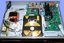
Here is an alternative internal view of HD970 and alternative upgrade:
1. Lower left hand side, the new clock power supply. The original M-Tron oscillator is still used. Why did the use 24.576MHz when this is a CD Player only. This is a DVD spec'd frequency 256 x 96KHz.
2. All post DAC circuitry has been disabled and no current drawn. We can now use the internal power supply before regulators. You can see the new output stage is powered from the input pins of the plus and negative IC Regs.
3. An entire new output stage using Passive Differential I/V (current canceling). This is kept Low Z and uses the FLTR 2.39V DAC pin to float it. The AC signal is very small and needs high gain and low noise. I use effectively a Moving Coil Phono circuit a la JLTi MC Phono, without EQ. No negative feedback. (See http://www.positive-feedback.com/Issue28/jlti_phono.htm). Minimal filtering - 50Khz single pole becoming 2-pole above 300KHz.
4. Replace plastic RCA output sockets with cryoed types. Signal single core wiring also cryoed.
5. Some SMD components fitted to lower back-EMF noise in the digital section.
6. Added a large bituminous loaded damping panel to Top Cover.
The end result? Very nice, a good and lively sound, even vibrant. Top end is quite good with plenty of nice detail. I would not describe as neither cold or warm but down the middle. Excellent bass IMO.
Joe R.
PS: George, it was two words?
Attachments
- Status
- This old topic is closed. If you want to reopen this topic, contact a moderator using the "Report Post" button.
- Home
- Source & Line
- Digital Source
- Harmon Kardon HD970:inside view