seems extreme, did you try the free RMAA to doublecheck?
http://audio.rightmark.org/products/rmaa.shtml
this collection of tests is getting pretty dated but even these older cards don't show 5 dB holes
http://www.pcavtech.com/soundcards/compare/index.htm
used old RMAA too, now the RMAA frequency plot is denser, plotted as a cont line
http://audio.rightmark.org/products/rmaa.shtml
this collection of tests is getting pretty dated but even these older cards don't show 5 dB holes
http://www.pcavtech.com/soundcards/compare/index.htm
used old RMAA too, now the RMAA frequency plot is denser, plotted as a cont line
easy to check a few sine tones in Audacity to find such a deep hole, also fft of white niose should work
http://audacity.sourceforge.net/
http://audacity.sourceforge.net/
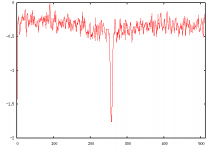
Since you guys seem to like this old-fashioned noise stuff, here is the result of a measurement using white gaussian noise!...
Yes, it seems the gap is still there... Tough it looks more narrow and smaller. But I would bet this is due the imperfection of using noise. TSP is much nicer!
I don't know what can be wrong in this board. I probably should tear it up and see if there aren't any strange capacitances.
Yes, it seems the gap is still there... Tough it looks more narrow and smaller. But I would bet this is due the imperfection of using noise. TSP is much nicer!
I don't know what can be wrong in this board. I probably should tear it up and see if there aren't any strange capacitances.
Attachments
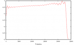
Here I am again... Guess what, nobody killed the charade!
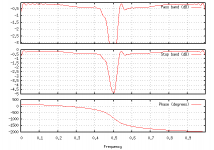
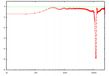
Yes, the strange hole was probably caused by the shitty connector I was using to make the loop. I connected through a small amp I made, and now the response looks better. Now it only has a small inclination, and that ripple... Still not sure what is caused by my amp, by my measurement technique (TSP) and what is due to the board itself. But looks pretty now!
Yes, the strange hole was probably caused by the shitty connector I was using to make the loop. I connected through a small amp I made, and now the response looks better. Now it only has a small inclination, and that ripple... Still not sure what is caused by my amp, by my measurement technique (TSP) and what is due to the board itself. But looks pretty now!
Attachments
Sorry if the incremental postings is annoying...
Well, this time I used just a single jack-RCA cable, and a small RCA-jack conversor.
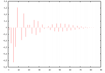
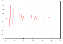
The ripples in the previous graph are because that plot was from the DFT of the truncated impulse response.
This plot here is truncating the impulse response after much more samples. This is not "realistic", but gets a better estimate of the true transfer function... Has to do with handling noise, and stuff, I don't know exactly.
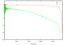
If you consider all samples, your transfer function looks noisy. If you cut it short, you get that ripples. This image here was from a response truncated at around 1900 samples. The original TSP I used had 2**12 (4k) samples, so this is like an intermediary choice... There is a little noise in the low frequencies, but the ripple from the truncation is very weak.
There is still a little ripple in the estimated TF tough, and now I'm inclined to believe that this is a true ripple from the board's filters. The green curve is the same one in "centibels".
Does anybody know what kind of filter should I expect? I could believe this is a 15-order Chebyshev, but I don't have experience with such large order analog filters... Is this feasible?
My next post will probably be from a measurement of the filter of the output of my electric guitar! =)
Well, this time I used just a single jack-RCA cable, and a small RCA-jack conversor.
The ripples in the previous graph are because that plot was from the DFT of the truncated impulse response.
This plot here is truncating the impulse response after much more samples. This is not "realistic", but gets a better estimate of the true transfer function... Has to do with handling noise, and stuff, I don't know exactly.
If you consider all samples, your transfer function looks noisy. If you cut it short, you get that ripples. This image here was from a response truncated at around 1900 samples. The original TSP I used had 2**12 (4k) samples, so this is like an intermediary choice... There is a little noise in the low frequencies, but the ripple from the truncation is very weak.
There is still a little ripple in the estimated TF tough, and now I'm inclined to believe that this is a true ripple from the board's filters. The green curve is the same one in "centibels".
Does anybody know what kind of filter should I expect? I could believe this is a 15-order Chebyshev, but I don't have experience with such large order analog filters... Is this feasible?
My next post will probably be from a measurement of the filter of the output of my electric guitar! =)
Attachments
- Status
- This old topic is closed. If you want to reopen this topic, contact a moderator using the "Report Post" button.
- Home
- Source & Line
- Digital Source
- Sound card transfer function