CD94 MKII Wiring Diagram
Hi Boky,
Herewith my detail DAC picture. It has 2 x TDA1541A S1 (Single Crown) but the mark has been removed because of glue of heatsink previously fitted. Need your help to send me the wiring of CD94 MKII to my email at wempie@parnaraya.net or wempie.pauned@hotmail.com. My audio hobby homepage at : http:/www.wempiepauned.com
Cheers
Wempie
Attachments
Re: CD94 MKII Wiring Diagram
I DO NOT HAVE CD94MKII circuit diagram. I will e-mail you the CD94 service manual.
Boky
Wempie said:Hi Boky,
Herewith my detail DAC picture. It has 2 x TDA1541A S1 (Single Crown) but the mark has been removed because of glue of heatsink previously fitted. Need your help to send me the wiring of CD94 MKII to my email at wempie@parnaraya.net or wempie.pauned@hotmail.com. My audio hobby homepage at : http:/www.wempiepauned.com
Cheers
Wempie
I DO NOT HAVE CD94MKII circuit diagram. I will e-mail you the CD94 service manual.
Boky
I've tried....
Hi. This is the qmail-send program at server.
I'm afraid I wasn't able to deliver your message to the following addresses.
This is a permanent error; I've given up. Sorry it didn't work out.
<wempie@parnaraya.net>:
Mail quota exceeded.
--- Below this line is a copy of the message.
Return-Path: <nsvircev@idx.com.au>
Received: (qmail 16804 invoked from network); 6 Sep 2007 22:15:16 -0000
Received-SPF: pass (server29.client.org: local policy)
Received: from mx-relay.idx.com.au (HELO mx-relay.idx.com.au) (203.14.30.1)
by server29.client.org (qpsmtpd/0.32) with ESMTP; Thu, 06 Sep 2007 22:15:15 +0000
Received: (from root@localhost)
by mx-relay.idx.com.au (8.11.6/8.11.2) id l86MEj009916
for wempie@parnaraya.net; Fri, 7 Sep 2007 08:14:45 +1000
Received: from PC ([203.19.8.192])
by mx-relay.idx.com.au (8.11.6/8.11.2) with ESMTP id l86LsLX08030
for <wempie@parnaraya.net>; Fri, 7 Sep 2007 07:54:22 +1000
From: "Nick Svircev" <nsvircev@idx.com.au>
To: <wempie@parnaraya.net>
Subject: CD94
Date: Fri, 7 Sep 2007 07:54:24 +1000
Message-ID: <000e01c7f0d0$7e0a5a60$c00813cb@PC>
MIME-Version: 1.0
Content-Type: multipart/mixed;
boundary="----=_NextPart_000_000F_01C7F124.4FB66A60"
X-Mailer: Microsoft Office Outlook 11
Thread-Index: Acfwz7AsrmjToJBdQpecEKLlgPbzeg==
X-MimeOLE: Produced By Microsoft MimeOLE V6.00.2900.3028
This is a multi-part message in MIME format.
------=_NextPart_000_000F_01C7F124.4FB66A60
Content-Type: multipart/alternative;
boundary="----=_NextPart_001_0010_01C7F124.4FB66A60"
------=_NextPart_001_0010_01C7F124.4FB66A60
Content-Type: text/plain;
charset="windows-1250"
Content-Transfer-Encoding: 7bit
Cheers,
Boky
Marantz CD-95 DAC Board
Hi Boky,
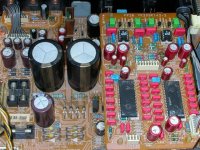
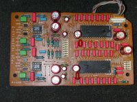
Herewith my DAC board attached, the caps are all replaced with Wima and ERO by previuos owner. Can you help me, I need to know the value of the caps arround the OP Amps the 4 square blue caps and another 4 Wima red caps located between the green caps and the blue caps. Those caps was replaced by the previous owner with parallel at the bottom however with (Silver mica) at the bottom to obtain the original value I quess, but paralleling with Silver mica is not correct I quess. The green caps are 5,600 pf and not parallel. As at your DAC board it shows 4 black cylindrical and 8 oval blue caps.
Regards
Hi Boky,
Herewith my DAC board attached, the caps are all replaced with Wima and ERO by previuos owner. Can you help me, I need to know the value of the caps arround the OP Amps the 4 square blue caps and another 4 Wima red caps located between the green caps and the blue caps. Those caps was replaced by the previous owner with parallel at the bottom however with (Silver mica) at the bottom to obtain the original value I quess, but paralleling with Silver mica is not correct I quess. The green caps are 5,600 pf and not parallel. As at your DAC board it shows 4 black cylindrical and 8 oval blue caps.
Regards
Attachments
green caps 5.6nF
red caps 18nF
blue caps 2.4nF
other values (around DAC chips) are readable from my DAC board photo.
I suggest you try polystyrenes 'cause overemphasised mid range....
WIMA polypropylenes are good, but may blow the mid range really too far...
Whatever you choice may be, do not bypass the audio-filter caps.
Good luck,
Boky
Hi Guys,
Very interesting post, I have just got one of these players and I am going to replace the entire output stage with a valve circuit. Google for Lampizator. I have done this already in a cambridge audio cd4se with amazing results and not it's time to do it with a decent dac chip.
I would be grateful if boxy could send a pdf of the service manual for the cd94Mk1, email address is clive.wills@googlemail.com
Cheers guys, a few interesting ideas in addition to the valve circuit to employ!
Clivers
Hi Boky,
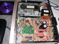
I have the LHH1000 but seems very difficult to find the service manual. I saw photos of the CD94 and it looks very similar to the LHH1000 transport. I would appreciate if you could email me the service manual for the CD94.
I am also looking for the 'clamping' belts, there are 2 of them, if I am not mistaken. The disk would not start if the belt slips. Where do you find your belts?
There is a SAA7220 in the transport. Is it important to 'change' the crystal there to a better 'clock'? or focus on the the DAC itself. Do not remember seeing a crystal next to the SAA7220 in the DAC.
Thanks.
skseah said:Hi Boky,
I have the LHH1000 but seems very difficult to find the service manual. I saw photos of the CD94 and it looks very similar to the LHH1000 transport. I would appreciate if you could email me the service manual for the CD94.
I am also looking for the 'clamping' belts, there are 2 of them, if I am not mistaken. The disk would not start if the belt slips. Where do you find your belts?
There is a SAA7220 in the transport. Is it important to 'change' the crystal there to a better 'clock'? or focus on the the DAC itself. Do not remember seeing a crystal next to the SAA7220 in the DAC.
Thanks.
I'll keep it on the ftp server for a week....
ClickMe
")
Rubber belts can be purchased from Wagner Electronics. You'll have to measure the old ones first. Download the Catalogue from Wagner web site and read the section that explains how to specify rubber belts dimensions, i.e. how to measure and order them.
Best Regards,
Boky
Best Regards,
Boky
Attachments
Hi Boky,
I got 3 of the 4 belts 1 ordered. 1 was short-shipped, however, I found a temp belt. After changing the belts, the drive does not open when I press the 'open' button. However, when I press 'close', the tray goes it (ie. after I manually pull it out), but I can hear a soft humming noise. And the disc does not turn. Any suggestion where to look? I checked all the ribbon cables, and they all are plugged in well.
Thanks & Best Regards
S K
skseah said:Hi Boky,
I got 3 of the 4 belts 1 ordered. 1 was short-shipped, however, I found a temp belt. After changing the belts, the drive does not open when I press the 'open' button. However, when I press 'close', the tray goes it (ie. after I manually pull it out), but I can hear a soft humming noise. And the disc does not turn. Any suggestion where to look? I checked all the ribbon cables, and they all are plugged in well.
Thanks & Best Regards
S K
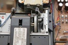
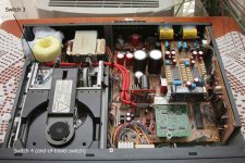
You have probably replaced the belts with larger ones and you have slipping, and / or you misaligned the switches 1, 2 and 3. Switch 4 is located somewhere underneath of the tray and I do not think that you had to temper with it – so the Switch 4 is probably okay.
Condition for Open function to operate successfully: Switch 3 closed, Switch 4 open (and maybe Switch 1 closed and Switch 2 open, but this is more important for laser to start checking for reflection, and then to start to spin the disk)
Condition for the spindle motor to start spinning the disk: Switch 1 closed, Switch 2 open, laser detected the reflection of the disk.
To replace the clamping belts (2 of them), you HAD to remove the metal plate that holds Switch 1 and Switch 2. However, you did not have to remove Switch 3 and Switch 4 to replace the tray belts (2 of them).
When you press OPEN, Switch 1 opens, Switch 2 closes (this indicates now that the tray can start to open!), Switch 3 opens, and Switch 4 closes. Now, if the Switch 4 is not closed, close function can not start to execute.
When you press CLOSE, Switch 4 will open and Switch 3 will close (this now indicates that the clamping process can start to execute), Switch 2 will open and Switch 1 will close. Now, the laser can check for the presence of the disk, and if YES, the spindle motor will spin the disk.
I expect that you did not position the clamping pulley / wheel that engages Switch 1 and Switch 2 correctly, or you have bad slipping happening so that this wheel can not reach its end position and engage both switches.
Carefully check everything once again and make sure that you:
1. Replaced the belts with SHORTER ones of the same cross-section
2. Positioned Switch 1 and Switch 2 correctly so that they can be engaged.
Good luck,
Regards,
Boky
Attachments
- Status
- This old topic is closed. If you want to reopen this topic, contact a moderator using the "Report Post" button.
- Home
- Source & Line
- Digital Source
- 94 mk II before / after