 oes the reset RC network time constant sufficient to put CS8416 into fully reset state at power up???
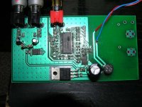
Thanks for sharing this!
I'm building it now but looking at the datasheet I'm not sure why pins 14-19 need to be set to 1/2Vcc? You have tied pin 26 (SD out) to GND via 47k, which shall place the chip in hardware mode. In hardware mode pins 14-19 are status output indicators, so am I safe to assume these can be left floating? It will make prototyping somewhat tidier if I can leave out the 12 47k resistors!
I'm building it now but looking at the datasheet I'm not sure why pins 14-19 need to be set to 1/2Vcc? You have tied pin 26 (SD out) to GND via 47k, which shall place the chip in hardware mode. In hardware mode pins 14-19 are status output indicators, so am I safe to assume these can be left floating? It will make prototyping somewhat tidier if I can leave out the 12 47k resistors!
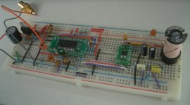
If it works on breadboard that's a good sign! Had to change the 0.1uF capacitor in the reset RC up to a larger value. I put 4.7uF but I'd recommend anything over 1uF.
The inductor is just experimental LRC filtering for the DAC supply, most of the noise on the output doesn't seem to be from the supply however as even when running the DAC from a totally seperate battery pack it still produces noise. Mostly above 20kHz it seems so I'll experiment with multi-pole output filters too.
The inductor is just experimental LRC filtering for the DAC supply, most of the noise on the output doesn't seem to be from the supply however as even when running the DAC from a totally seperate battery pack it still produces noise. Mostly above 20kHz it seems so I'll experiment with multi-pole output filters too.
Attachments
Hardware mode configuration
In your board, about pins:
14 connect 47K to VCC or GND
15 connect 47K to VCC or GND
16 connect 47K to VCC or GND
17 connect 47K to VCC or GND
18 connect 47K to VCC or GND
19 connect 47K to VCC or GND
20 connect 47K to VCC or GND
Hi All
I am new on this board and want to share my simple project with CS8416 and CS4334. Any comments are welcome. Thanks in advance George
In your board, about pins:
14 connect 47K to VCC or GND
15 connect 47K to VCC or GND
16 connect 47K to VCC or GND
17 connect 47K to VCC or GND
18 connect 47K to VCC or GND
19 connect 47K to VCC or GND
20 connect 47K to VCC or GND
- Status
- This old topic is closed. If you want to reopen this topic, contact a moderator using the "Report Post" button.
- Home
- Source & Line
- Digital Source
- simple DAC with CS8416