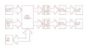
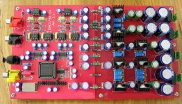
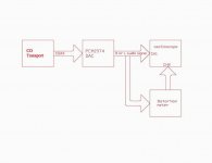
I'm building a 2xpcm1794 dac too (perhaps 4 x pcm1794) but directly with the I2S output of my CDPRO2. I like your design and the color of your pcb ") It seems you've done it in single face the front face is for the separate grounds ? Are you coupling the grounds and how ( capacitors, ... )?
It seems you've done it in single face the front face is for the separate grounds ? Are you coupling the grounds and how ( capacitors, ... )?
what about your I/V opamp choice ? I have 6 opa827 and I'd like to test them in my DAC ...
It seems you've done it in single face the front face is for the separate grounds ? Are you coupling the grounds and how ( capacitors, ... )?what about your I/V opamp choice ? I have 6 opa827 and I'd like to test them in my DAC ...
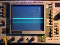
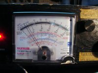
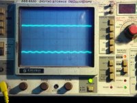
I used the Samplitude software to generate the test signal and burned on to a CD.
the CD track:
1) mute
2) -90db 1Khz Sine
3) -80db 1Khz Sine
4) -70db 1Khz Sine
5) -60db 1khz sine
6) -50db 1khz sine
7) -40db 1khz sine
8) -30db 1khz sine
9) -20db 1khz sine
10) -10db 1khz sine
11) 0db 1khz sine
12) CH L 100Hz sine
13) CH LR 100Hz sine
14) CH R 100Hz sine
15) CH L 1KHz sine
16) CH LR 1KHz sine
17) CH R 1KHz sine
18) CH L 10KHz sine
19) CH LR 10KHz sine
20) CH R 10KHz sine
21) CH L 20KHz sine
22) CH R 20KHz sine
23) CH LCR sine
24) -6db 100Hz Square
25) -6db 1kHz Square
26) -6db 10kHz Square
27) cannon 18
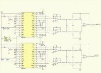
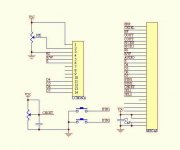
my double pcm1792DAC I/V use opa604.
schemaic post to later.
the CD track:
1) mute
2) -90db 1Khz Sine
3) -80db 1Khz Sine
4) -70db 1Khz Sine
5) -60db 1khz sine
6) -50db 1khz sine
7) -40db 1khz sine
8) -30db 1khz sine
9) -20db 1khz sine
10) -10db 1khz sine
11) 0db 1khz sine
12) CH L 100Hz sine
13) CH LR 100Hz sine
14) CH R 100Hz sine
15) CH L 1KHz sine
16) CH LR 1KHz sine
17) CH R 1KHz sine
18) CH L 10KHz sine
19) CH LR 10KHz sine
20) CH R 10KHz sine
21) CH L 20KHz sine
22) CH R 20KHz sine
23) CH LCR sine
24) -6db 100Hz Square
25) -6db 1kHz Square
26) -6db 10kHz Square
27) cannon 18
my double pcm1792DAC I/V use opa604.
schemaic post to later.
Attachments
Hi skygtr,
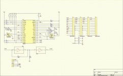
Thanks for the schematic.
Do you have the resistors and condensator values for the I/V and the differential amp ? I'm simulating my circuit and I'm interested to compare You put condensators between th in + and the in - of the diff amp ? I've seen them in some datasheets. Could you explain ?
Thanks in advance
Thanks for the schematic.
Do you have the resistors and condensator values for the I/V and the differential amp ? I'm simulating my circuit and I'm interested to compare
You put condensators between th in + and the in - of the diff amp ? I've seen them in some datasheets. Could you explain ?Thanks in advance
- Status
- This old topic is closed. If you want to reopen this topic, contact a moderator using the "Report Post" button.
- Home
- Source & Line
- Digital Source
- my double PCM1794DAC projet