Hi all,
Just a quick show of a little modification I've done to a Meridian 565 home cinema processor..
Even though it's quite old (the PCB's date from 1994!) it still outperforms many of the late 1990's offerings from e.g. Rotel. Looking inside gives a clear idea why; the components used are of high quality, especially the analog sections. Proper (not NE5532) opamps, MKP and polystyrene caps, shielded A/D section, and the best 18-bit DAC available at the time. Furthermore the chassis is incredibly inert and well-damped at the inside and outside, the digital and analog sections are well-isolated, and run from separate transformer secondaries. This is quite a bit better than many other multichannel processors.
It's features are also very good for its time, with adjustable crossover frequencies, phase relationship between all the speakers, protection levels for all channels, re-assignable outputs (if not used the side channels can be used for discrete subwoofers), and programmable sources with macros with all their settings.
The MAIN reason I bought it though, is because it has S/PDIF outputs for all its 8 post-processed channels. It's only natural that HT receivers skimp on the DAC sections inside since 6/8 channels are needed which makes it expensive as well as space consuming, and the eventual sound quality is often directly related to the quality of these sections. Look inside even high-end ones and the DAC sections are typically on par with fairly so-so dedicated stereo DAC's.
This Meridian on the other hand has digital outputs, intended for using with Meridian speakers along with the COMMS connection, but it really is just S/PDIF along with a data communications bus. So, rather than trying feeble methods of replacing opamps and bypass caps etc as many people here do with their AV receivers/processors, I'm currently designing a dedicated high-end 8-channel external DAC. Given for how little these processors go for (I got mine, the latest version with DTS as well for $500 on eBay), it's a very good base to build a serious processor from. Despite it, its analog section is actually quite good and even if used as a two-channel DAC it sounds very good, quite better than the Rotel RSP985 THX and Lexicon MC1 for example that I compared it with. The home cinema processing was also better than the Rotel, and more or less on par with the Lexicon. Add the proper DAC and it should really sing.
However, I found the power supply to be seriously lacking, and if one looks closely it's evident that the designers had underestimated the power needed at the last minute - many of the regulators that has footprints on the PCB's are bolted off-board onto the chassis with wires running to the board.
The puny frame transformer was way too small and got scorching hot. Its load regulation was very poor and the output dropped severely when turned on from standby, and then further when the processors kick in. Putting a scope on the post-rectified DC showed 500mV 50Hz ripple, and some of it leaked through the subsequent regulators.
Upgrading is always a nice idea, but there wasn't much to upgrade. The opamps were quite adequate TLE2037's, the power electrolytics Rubycon and the signal ones Nichicon Muse. That and given that it's not very old and that the assembly is a bit complex, I've decided that it's not worth it. The PSU did need some attention however, and since there was quite a bit of room in the chassis it was easy to do so.
I could have just replaced the transformer with a more powerful one, but that would not have solved the ripple issue. So, given that there's a lot of open space available, I opted for a proper pre-regulated DC supply. The transformer got replaced with a 100VA toroid (also two secondary sets), and two identical regulated PSU boards. They deliver the same +-10VDC as the original's post-rectified. I didn't bother trying to bypass the rectifiers, the boards would have had to be removed and I had enough headroom to keep them in.
The boards are simple and cost-effective, and many of it scored from old projects: rectifier, CRC filter, regulator, capacitor bank. The regulators are LT1764/1185, the input caps Rubycon, the output caps close to the regulators are 10uF tantalum and 220uF Panasonic FC, followed by 2x2200uF Nichicon per rail. The heatsinks came from a PC power supply. Total cost for everything was less than $25, and took a weekend's time. The only real problems were the dropping resistor on the positive digital supply had to be changed from a 10ohm 2W to a 0.47ohm 5W since I didn't know it draws around 1A, and adding a thermister to the incoming AC since the toroid and large capacitor bank kept blowing the fuse.
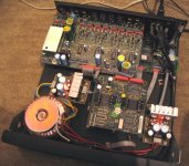
Here are pictures taken of the modified unit. The top PCB contains the A/D and D/A sections (the A/D inside a Faraday cage), below it the digital I/O and interfacing, and at the bottom the processors. The other two boards with the heatsinks are my regulators, with the toroid at the bottom left.
Audible improvement? No idea, I never listened to it before modding it. However, the DC feeding the processor's regulators has no ripple visible on a scope, and noise below 30mVpp. Compared to the original 500mV it's a very noticeable reduction, and the analog output is completely silent. All in all quite a satisfactory improvement at very low time and cost. One other improvement I'd still like to do is to bypass the optical input and multiplexers etc. feeding the CS8412 S/PDIF receiver and connect a pulse transformer directly to the receiver pins, but given the location of the chip it's not a trivial task.
Just a quick show of a little modification I've done to a Meridian 565 home cinema processor..
Even though it's quite old (the PCB's date from 1994!) it still outperforms many of the late 1990's offerings from e.g. Rotel. Looking inside gives a clear idea why; the components used are of high quality, especially the analog sections. Proper (not NE5532) opamps, MKP and polystyrene caps, shielded A/D section, and the best 18-bit DAC available at the time. Furthermore the chassis is incredibly inert and well-damped at the inside and outside, the digital and analog sections are well-isolated, and run from separate transformer secondaries. This is quite a bit better than many other multichannel processors.
It's features are also very good for its time, with adjustable crossover frequencies, phase relationship between all the speakers, protection levels for all channels, re-assignable outputs (if not used the side channels can be used for discrete subwoofers), and programmable sources with macros with all their settings.
The MAIN reason I bought it though, is because it has S/PDIF outputs for all its 8 post-processed channels. It's only natural that HT receivers skimp on the DAC sections inside since 6/8 channels are needed which makes it expensive as well as space consuming, and the eventual sound quality is often directly related to the quality of these sections. Look inside even high-end ones and the DAC sections are typically on par with fairly so-so dedicated stereo DAC's.
This Meridian on the other hand has digital outputs, intended for using with Meridian speakers along with the COMMS connection, but it really is just S/PDIF along with a data communications bus. So, rather than trying feeble methods of replacing opamps and bypass caps etc as many people here do with their AV receivers/processors, I'm currently designing a dedicated high-end 8-channel external DAC. Given for how little these processors go for (I got mine, the latest version with DTS as well for $500 on eBay), it's a very good base to build a serious processor from. Despite it, its analog section is actually quite good and even if used as a two-channel DAC it sounds very good, quite better than the Rotel RSP985 THX and Lexicon MC1 for example that I compared it with. The home cinema processing was also better than the Rotel, and more or less on par with the Lexicon. Add the proper DAC and it should really sing.
However, I found the power supply to be seriously lacking, and if one looks closely it's evident that the designers had underestimated the power needed at the last minute - many of the regulators that has footprints on the PCB's are bolted off-board onto the chassis with wires running to the board.
The puny frame transformer was way too small and got scorching hot. Its load regulation was very poor and the output dropped severely when turned on from standby, and then further when the processors kick in. Putting a scope on the post-rectified DC showed 500mV 50Hz ripple, and some of it leaked through the subsequent regulators.
Upgrading is always a nice idea, but there wasn't much to upgrade. The opamps were quite adequate TLE2037's, the power electrolytics Rubycon and the signal ones Nichicon Muse. That and given that it's not very old and that the assembly is a bit complex, I've decided that it's not worth it. The PSU did need some attention however, and since there was quite a bit of room in the chassis it was easy to do so.
I could have just replaced the transformer with a more powerful one, but that would not have solved the ripple issue. So, given that there's a lot of open space available, I opted for a proper pre-regulated DC supply. The transformer got replaced with a 100VA toroid (also two secondary sets), and two identical regulated PSU boards. They deliver the same +-10VDC as the original's post-rectified. I didn't bother trying to bypass the rectifiers, the boards would have had to be removed and I had enough headroom to keep them in.
The boards are simple and cost-effective, and many of it scored from old projects: rectifier, CRC filter, regulator, capacitor bank. The regulators are LT1764/1185, the input caps Rubycon, the output caps close to the regulators are 10uF tantalum and 220uF Panasonic FC, followed by 2x2200uF Nichicon per rail. The heatsinks came from a PC power supply. Total cost for everything was less than $25, and took a weekend's time. The only real problems were the dropping resistor on the positive digital supply had to be changed from a 10ohm 2W to a 0.47ohm 5W since I didn't know it draws around 1A, and adding a thermister to the incoming AC since the toroid and large capacitor bank kept blowing the fuse.
Here are pictures taken of the modified unit. The top PCB contains the A/D and D/A sections (the A/D inside a Faraday cage), below it the digital I/O and interfacing, and at the bottom the processors. The other two boards with the heatsinks are my regulators, with the toroid at the bottom left.
Audible improvement? No idea, I never listened to it before modding it. However, the DC feeding the processor's regulators has no ripple visible on a scope, and noise below 30mVpp. Compared to the original 500mV it's a very noticeable reduction, and the analog output is completely silent. All in all quite a satisfactory improvement at very low time and cost. One other improvement I'd still like to do is to bypass the optical input and multiplexers etc. feeding the CS8412 S/PDIF receiver and connect a pulse transformer directly to the receiver pins, but given the location of the chip it's not a trivial task.
Attachments
- Status
- This old topic is closed. If you want to reopen this topic, contact a moderator using the "Report Post" button.