Hi tubee!
PCM56 - good way to building DAC. But some circuits not correct.
Left&right DAC`s must be latched simoultanosly, but NOT independed. Is this RED BOOK of CD standard.
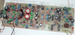
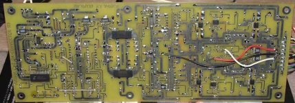
Look my DAC on PCM56.
I use CS8414 with double buffered data mode. If master-clock of CD is 11,2896 MHz than that clock may be transmitted to DAC and reclock all signals to PCM56 for jitter reduce.
PCM56 - good way to building DAC. But some circuits not correct.
Left&right DAC`s must be latched simoultanosly, but NOT independed. Is this RED BOOK of CD standard.
Look my DAC on PCM56.
I use CS8414 with double buffered data mode. If master-clock of CD is 11,2896 MHz than that clock may be transmitted to DAC and reclock all signals to PCM56 for jitter reduce.
Attachments
Zoran said:
Are You using the M0 to M3 pins connected like in the first diagram
Did You try maybe the other way to convert I to V like I-buffer?
Yes, like in upper schematic.
I-buffer???? I use passive to avoid any active devices / feedback loops.
I grabbed 1:10 and 1:15 audio transformers today and will give them a try.
That allows to reduce I/V resistor value and skip buffer-amp.
I think I need a low impedance analog filter for the most simple setup:
n x PCM56 - R - analog filter - transformer
or
n x PCM56 - R - transformer - analog filter
That allows to reduce I/V resistor value and skip buffer-amp.
I think I need a low impedance analog filter for the most simple setup:
n x PCM56 - R - analog filter - transformer
or
n x PCM56 - R - transformer - analog filter
Hi Bernard.
Now it's obvious for me. Did'nt try passive I/V yet, want to optimise logic first.
After some changes and headphone listening tests, i found out whats going on with 1 channel. First i added a small extra time delay with 2 cascaded inverters in LE line from lower dac, this dac gets LE direct.
Listening test reveiled no improvement, still a small digital noise, i estimate at -65dB or so. Description of what i heard: a sort of lispeling sound, right after i press 'Play' and when laser hits the track. But when then music softly starts, the noise is getting less obvious. The noise is "around" the music, and like a lispeling of a FM tuner slightly out of tune. MSB adjust helped slightly but didn't cure it. After swapping R / L dac noise kept on the same channel so it must be the logic. Extra decoupling of -5V to MSB adjust schematic did'nt help.
Maybe a better selected PCM will cure the noise. Unlikely because swapping didn't solve problem.
Maybe a small ground wiring error, and one dac keeps picking up noise. I connected Gnd from cdp (near 7210) to Gnd dacs/logic pcb to I/V pcb with rca's. There goes a gnd wire from 7210 to Kwak 7 Pcb too, will unscrew the clock and fiddle around with pcb, maybe it helps.
Added small 330pF styro cap across 100k bleeding R. (Pedja recom. 100p to 1N) to filter some hf noise away, and bypassed MKP, so now its dc coupled, 5 mV is not a lot.
Listening test: With MSB adjust the lispeling is less obvious, and allmost not hearable on normal volume (but like some louder )
)
The treble roll of starts about 10k and that's why i miss some freshness in sound. Soundstage is some mid forwarded, but overall it's rather relaxed, a good sign. Depth of soundstage is not very deep, but delaying of echoes are very obvious decaying, good sign again. Mids is still slightly distorted, and treble too slightly, but less compared to 1541 nonos (that one had 4 transistor simple I/V though)
Listening with 1541 nonos i had somewhat "rollercoaster feeling", (a wildness) pcm56 is more relaxed, but has the same nonos features: phase errors are gone, analog TT feeling, you are better involved with music, harmonics are more displayed (guitar plucking, and when player is thumping at guitar-case you can hear nicely this typical sound in the recording studio. Also the small ambient noises aound voices are very obvious.
On the contrary, some tones can oversound other instruments, and then the nonos seems some less detailed compared to digitally OS'ed music. This can also be by the slight distorsion a single PCM56 can give. But again, less then the 1541 nonos.
I have some hearing problems, but can hear more easy in the music with this nonos PCM56 compared to modded TDA1541 with SAA7220 dig. OS.
Sorry for these hazy descriptions of the soundQ, but that's how i hear it.
So this BB is worthwile to work further with overall!
I am thinking to build a I2S-dac with four in phase shifted PCM56's, maybe K grades. Nice compact to put in cdp, cool working, MSB adjust added ofcourse. With this setup it will become a 4 X hardware-oversampled dac. Have a 6922 tube lying, so will try passive I/V with tubed amplification to 2V~.
I try to cancel MSB errors by combination of 4 preselected chips.
Ideally it would be possible with only two chips per channel
Now it's obvious for me. Did'nt try passive I/V yet, want to optimise logic first.
After some changes and headphone listening tests, i found out whats going on with 1 channel. First i added a small extra time delay with 2 cascaded inverters in LE line from lower dac, this dac gets LE direct.
Listening test reveiled no improvement, still a small digital noise, i estimate at -65dB or so. Description of what i heard: a sort of lispeling sound, right after i press 'Play' and when laser hits the track. But when then music softly starts, the noise is getting less obvious. The noise is "around" the music, and like a lispeling of a FM tuner slightly out of tune. MSB adjust helped slightly but didn't cure it. After swapping R / L dac noise kept on the same channel so it must be the logic. Extra decoupling of -5V to MSB adjust schematic did'nt help.
Maybe a better selected PCM will cure the noise. Unlikely because swapping didn't solve problem.
Maybe a small ground wiring error, and one dac keeps picking up noise. I connected Gnd from cdp (near 7210) to Gnd dacs/logic pcb to I/V pcb with rca's. There goes a gnd wire from 7210 to Kwak 7 Pcb too, will unscrew the clock and fiddle around with pcb, maybe it helps.
Added small 330pF styro cap across 100k bleeding R. (Pedja recom. 100p to 1N) to filter some hf noise away, and bypassed MKP, so now its dc coupled, 5 mV is not a lot.
Listening test: With MSB adjust the lispeling is less obvious, and allmost not hearable on normal volume (but like some louder
)The treble roll of starts about 10k and that's why i miss some freshness in sound. Soundstage is some mid forwarded, but overall it's rather relaxed, a good sign. Depth of soundstage is not very deep, but delaying of echoes are very obvious decaying, good sign again. Mids is still slightly distorted, and treble too slightly, but less compared to 1541 nonos (that one had 4 transistor simple I/V though)
Listening with 1541 nonos i had somewhat "rollercoaster feeling", (a wildness) pcm56 is more relaxed, but has the same nonos features: phase errors are gone, analog TT feeling, you are better involved with music, harmonics are more displayed (guitar plucking, and when player is thumping at guitar-case you can hear nicely this typical sound in the recording studio. Also the small ambient noises aound voices are very obvious.
On the contrary, some tones can oversound other instruments, and then the nonos seems some less detailed compared to digitally OS'ed music. This can also be by the slight distorsion a single PCM56 can give. But again, less then the 1541 nonos.
I have some hearing problems, but can hear more easy in the music with this nonos PCM56 compared to modded TDA1541 with SAA7220 dig. OS.
Sorry for these hazy descriptions of the soundQ, but that's how i hear it.
So this BB is worthwile to work further with overall!
I am thinking to build a I2S-dac with four in phase shifted PCM56's, maybe K grades. Nice compact to put in cdp, cool working, MSB adjust added ofcourse. With this setup it will become a 4 X hardware-oversampled dac. Have a 6922 tube lying, so will try passive I/V with tubed amplification to 2V~.
Hi Tubee
there should not be any lispeling or noise.
The pure sound will not be there until you get rid of it.
You could trace that problem with a scope.
Compare L and R channels @ -60dB and find a difference.
Again: Forget the K-grades. The grades are determined without MSB adjust and assure a minimum of performance unadjusted plug and play, that lies far behind a selected & adjusted ( what you have ) chip.
Try passive.
Perhaps try CS8412.
You can get rid of the rolloff with analog filtering.
Phase shifted PCM56's introduce nonlinearity.
Hi Alp
Nice dac, did you edged PCB's yourself, or let it done professionally?
Yes PCM56 is worthwile, i did'nt expect this because the by this time allmost everyone wants the overly culted TDA1541. And have about 8 of them @ my premisis too btw.
The comment to keep LE for both dac's, has another fact: no timing errors, both dacs starts to decode at the same time.
With the glue logic i use there is a timing error of 16 bit @ 2.8Mhz, it is a few mm of speaker of displacement, the TDA1541 dac has this also. In the eighties that was one of the discussing points of the contra-Philips/(Marantz) clan, along with the single laserbeam vs 3 beam laser discussion. (those old Philips CDM's still play btw)
With This schem.:
http://www.geocities.com/nonospcm1704/universal_shifter.gif
Of site: http://www.geocities.com/nonospcm1704/universal_shifter.html
the timing errors are gone. But it has rather high chipcount for first experiments. The schematic can be simplified; 74/74 can be omitted with single ended operated dac's. Data is shifted in R-L and WS-LE untouched. The PCM's LE pin only works on falling edge of LE and pcm's decode simultane along with the shifted data.
Another PCM56 fact: less parts used around dac, no 14 decoupling caps, no oscillator cap (or dem reclock) the 1541 needs.
I used for PCM56 PS two 75L05 and two 79/05 regs. But i think the analog -5V supply can be cancelled, i don't use the internal opamp. Not sure about this.
Hi Bernard
then only with a sin x/x or something something like that-called filter? (in short: resonant filter)
Ok this will simple things up again.
Will try to find noise problem with scope this evening. It's a loan scope, and the horizontal beam is placed vertical!
You can get rid of the rolloff with analog filtering.
then only with a sin x/x or something something like that-called filter? (in short: resonant filter)
Phase shifted PCM56's introduce nonlinearity.
Ok this will simple things up again.
Will try to find noise problem with scope this evening. It's a loan scope, and the horizontal beam is placed vertical!
tubee said:
Another PCM56 fact: less parts used around dac, no 14 decoupling caps, no oscillator cap (or dem reclock) the 1541 needs.
I used for PCM56 PS two 75L05 and two 79/05 regs.
I have tied V+a and V+d together as well as negative supplies.
Null problemo.
Another PCM56 fact: It is mono.
I have one TDA1541 R1.
One channel is excellent while the other is mediocre.

I have one TDA1541 R1.
One channel is excellent while the other is mediocre.
Cut it in half i would say
Oh listen to pcm right now: deep bass is deeper, but overall bass response some leaner. But 1541 has a more boomy bass, now i can remove bass pipe stuffings again from the ML-TQWT's. Another fact: PCM is faster, at least it sounds faster to me. 1541 emphasises upper bass mid range, slightly "thicker" sound. PCM56 has a more clean sound indeed. (a little tube or fet-like compared to 1541: is more like bipolar transistor)
Listen btw to The Blue Nile, walk around rooftops, Linn records.
What did you do with Gnd Bernard, i connected it underneath dac analog & digital gnd together.
Hi tubee!
...Nice dac, did you edged PCB's yourself, or let it done professionally?
Yourself. On my kitchen.
...Yes PCM56 is worthwile, i did'nt expect this because the by this time allmost everyone wants the overly culted TDA1541.
I have crowned 1541, but I think that TDA no more cheapest then 56P-K.
...The comment to keep LE for both dac's, has another fact: no timing errors, both dacs starts to decode at the same time.
With the glue logic i use there is a timing error of 16 bit @ 2.8Mhz, it is a few mm of speaker of displacement...
I many times hear about "few mm"
Phase shift is corellated with playing frequency. Some years ago I make expirience: two DAC, one of this have "glue logic" (100% clone AudioNote x.1 DAC board) and independed LE, second DAC have one LE for both DACs.
Play wide freq white noise from TEST CD.
And what I hear? Very, very interesting effect with "glue logic DAC" - source of noise moving nearest center of my speakers.
With correct scheme (one LE for both DACs), source of noise stay in centre between speakers.
No comments anymore...
...the timing errors are gone. But it has rather high chipcount for first experiments. The schematic can be simplified; 74/74 can be omitted with single ended operated dac's. Data is shifted in R-L and WS-LE untouched. The PCM's LE pin only works on falling edge of LE and pcm's decode simultane along with the shifted data.
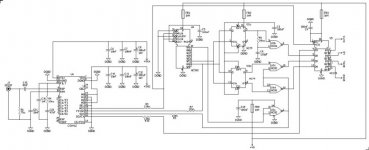
I don`t use shift registers. I use breaked bitclock. But 1851 work good with use FCK from 8414 as LE. PCM56 - dont work (noise in right channel). For correct work PCM56 you need some different square of FCK.
"Heart" circuit of my DAC attached. Sorry, but full circuit is not complite.
...I used for PCM56 PS two 75L05 and two 79/05 regs. But i think the analog -5V supply can be cancelled, i don't use the internal opamp. Not sure about this.
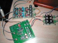
I use LT317\337 (Linear Tech STRONGLY!) for digital and discrete shunt regulator for analogue. I\V Opamp, GIC-filter, fet-input opamp as output buffer.
...Nice dac, did you edged PCB's yourself, or let it done professionally?
Yourself. On my kitchen.
...Yes PCM56 is worthwile, i did'nt expect this because the by this time allmost everyone wants the overly culted TDA1541.
I have crowned 1541, but I think that TDA no more cheapest then 56P-K.
...The comment to keep LE for both dac's, has another fact: no timing errors, both dacs starts to decode at the same time.
With the glue logic i use there is a timing error of 16 bit @ 2.8Mhz, it is a few mm of speaker of displacement...
I many times hear about "few mm"
Phase shift is corellated with playing frequency. Some years ago I make expirience: two DAC, one of this have "glue logic" (100% clone AudioNote x.1 DAC board) and independed LE, second DAC have one LE for both DACs.
Play wide freq white noise from TEST CD.
And what I hear? Very, very interesting effect with "glue logic DAC" - source of noise moving nearest center of my speakers.
With correct scheme (one LE for both DACs), source of noise stay in centre between speakers.
No comments anymore...
...the timing errors are gone. But it has rather high chipcount for first experiments. The schematic can be simplified; 74/74 can be omitted with single ended operated dac's. Data is shifted in R-L and WS-LE untouched. The PCM's LE pin only works on falling edge of LE and pcm's decode simultane along with the shifted data.
I don`t use shift registers. I use breaked bitclock. But 1851 work good with use FCK from 8414 as LE. PCM56 - dont work (noise in right channel). For correct work PCM56 you need some different square of FCK.
"Heart" circuit of my DAC attached. Sorry, but full circuit is not complite.
...I used for PCM56 PS two 75L05 and two 79/05 regs. But i think the analog -5V supply can be cancelled, i don't use the internal opamp. Not sure about this.
I use LT317\337 (Linear Tech STRONGLY!) for digital and discrete shunt regulator for analogue. I\V Opamp, GIC-filter, fet-input opamp as output buffer.
Attachments
Hi Alp
So you used the stopped clock operation like depicted on AD's AN207 application note. Bernard has posted a schematic of it in another thread: http://www.diyaudio.com/forums/showthread.php?postid=1120321#post1120321
Nice to hear about the concequence of the timing error.
Have somewhere a schematic of discrete shunt PS, never tried it.
The cdp is working now for few hours, every hours sound opens up further (Cerafines on AD844 I/V burn in, and modded overall PS of cdp)
tubee said:
What did you do with Gnd Bernard, i connected it underneath dac analog & digital gnd together.
All gnd tied together.
For the 1541 one could use the good left channel of one chip and the good right channel of another.
Hi
...So you used the stopped clock operation like depicted on AD's AN207 application note.
NO. I use 8412 (or 8414) in slave-mode. 74HC590 divide master-clock (Fs, 64 Fs), 74HC02 - break BCK and some shift square of FCK, 74HC175 - reclock all signals for DACs.
...Have somewhere a schematic of discrete shunt PS, never tried it.
simplest circuit attached. correct nominals for need output voltage. For finest work needed current across 1837\4793 approx. 100 mA
...The cdp is working now for few hours, every hours sound opens up further (Cerafines on AD844 I/V burn in, and modded overall PS of cdp)
I don`t like Ceafines - dry bass sound. Black Gate non-polar - very nice.
Sorry, but I cannot publish type of my op-amps. Not needed adversting on this forum. Sorry.
Attachments
Hi Alp.
Sorry to say, but i think BG's exotic ones, above the standard thus cheap ones, are not special to me, bad experience. http://www.diyaudio.com/forums/showthread.php?postid=1118246#post1118246
But a standard BG as Cathode decoupling in phono tube stage did wonders. Hum dropped immediately,
Sanyo oscon is suggested as good in dig (tried once), and panasonic is very nice in analog ps(in my poweramp) But the good old standard blue Philips cap does not bad either.
I soldered a lot of tantalium smd caps & smd beads under the pcm & logic. I like smd, short tracks, easy to solder. All logic lines have 100 ohm stopping resistors to each gate, to keep hf path short, decoupling at chip does the rest (Guido Tents decoupling guidelines)
Oh yes i see Alp, you used the CS8412, no I2S transition needed.
Did you want to say LM4562?
I ordered some samples at ....., (no not National) they cancelled/removed the request. Its getting difficult, we poor diy ers have to pay a lot more for our experiments. Paid once 12$/each for op275, they're lying somewhere with dust on it.
Sorry to say, but i think BG's exotic ones, above the standard thus cheap ones, are not special to me, bad experience. http://www.diyaudio.com/forums/showthread.php?postid=1118246#post1118246
But a standard BG as Cathode decoupling in phono tube stage did wonders.
Hum dropped immediately,Sanyo oscon is suggested as good in dig (tried once), and panasonic is very nice in analog ps(in my poweramp) But the good old standard blue Philips cap does not bad either.
I soldered a lot of tantalium smd caps & smd beads under the pcm & logic. I like smd, short tracks, easy to solder. All logic lines have 100 ohm stopping resistors to each gate, to keep hf path short, decoupling at chip does the rest (Guido Tents decoupling guidelines)
Oh yes i see Alp, you used the CS8412, no I2S transition needed.
Did you want to say LM4562?
I ordered some samples at ....., (no not National) they cancelled/removed the request. Its getting difficult, we poor diy ers have to pay a lot more for our experiments. Paid once 12$/each for op275, they're lying somewhere with dust on it.
tubee said:
Rfbrw, did you some special things like DSP with FPGA?
Nothing serious. Only recently have the big fpga devices become cheap enough for home use. Need to find time to lay out a pcb.
tubee said:
But it has rather high chipcount for first experiments. The schematic can be simplified; 74/74 can be omitted with single ended operated dac's. Data is shifted in R-L and WS-LE untouched. The PCM's LE pin only works on falling edge of LE and pcm's decode simultane along with the shifted data.
How many chips are acceptable ?
Hi Rfbrw
Do you have software on pc for pcb layout? I had for a while but it costed me so much time, i simply draw the pcb myself for a Kwak clock 7 with simple to use TCI softw. But with more complicated schematics some advanced software is very welcome.
As said before the glue logic i tried has only 2 shift registers and 1 inverter, nice to start with. The universal data shifter uses 8 registers and a Nand gate.
I suggest its not the best way to use a lot of logic and chips, when a simple design can do the same. When a larger chipcount is working better it has to be that way.
I am working on a stopped clock schematic, ALP made me think about it because of his of phase and listening test comments.
When i was showering figured out how to solve noise problem on 1 channel. Will post results when this may be succesful.
Great advantage here on diyaudio, we post our first try outs, and others can give their suggestions, very welcome, thanks.
Do you have software on pc for pcb layout? I had for a while but it costed me so much time, i simply draw the pcb myself for a Kwak clock 7 with simple to use TCI softw. But with more complicated schematics some advanced software is very welcome.
How many chips are acceptable ?
As said before the glue logic i tried has only 2 shift registers and 1 inverter, nice to start with. The universal data shifter uses 8 registers and a Nand gate.
I suggest its not the best way to use a lot of logic and chips, when a simple design can do the same. When a larger chipcount is working better it has to be that way.
I am working on a stopped clock schematic, ALP made me think about it because of his of phase and listening test comments.
When i was showering figured out how to solve noise problem on 1 channel. Will post results when this may be succesful.
Great advantage here on diyaudio, we post our first try outs, and others can give their suggestions, very welcome, thanks.
- Status
- This old topic is closed. If you want to reopen this topic, contact a moderator using the "Report Post" button.
- Home
- Source & Line
- Digital Line Level
- SAA7210 to PCM56, a Dutch-American connection