I/V TDA1541A S1 DAC
I don't think is wise to start another thread on the same subject, so here is my question.
I'm replacing the CFB AD844 I/V originally proposed by Jung on his Pooge articles on the CDB650 CDP with the LM6181 CFB opamp.
Sure I'm doing somethig wrong so please give some advise.
The Dac connection is going to the inverting input of the opamp through a 220 Ohms and the feed back is a 1K Ohms. I also have a 47 Ohms resistor at the output to isolate cable capacitance.
The result is nice but with a lot of noise indeed.
What's wrong?
Why is it going through 220 ohms??????? And why no output filter?????
Just in case anyone cares.....I used the AD846 as an I/V before I came up wit the one you guys are trying to reverse engineer.
The reason why is that our dealers did not like the sound of the CFB I/V.
And while we are at it......................here is one more for you guys to ponder......mostly Elso [joke]........
On the op-amp I/V stages, I pumped a 1.8 mA current into the input to cancel out the unipolar current the '1541 puts out. And that current was servo controlled.
Jocko
Jocko Homo said:On the op-amp I/V stages, I pumped a 1.8 mA current into the input to cancel out the unipolar current the '1541 puts out. And that current was servo controlled.
AND?

NOT FUNNY!
I know what's in your board. I will not spread the knowledge.
I have enough of pesting other forummembers!
I have enough of this hobby. Did throw my DAC against the wall. Bang, what a bad sound!!!
END OF STORY->

Jocko, Not funny.Jocko Homo said:Why is it going through 220 ohms??????? And why no output filter?????
Just in case anyone cares.....I used the AD846 as an I/V before I came up wit the one you guys are trying to reverse engineer.
The reason why is that our dealers did not like the sound of the CFB I/V.
And while we are at it......................here is one more for you guys to ponder......mostly Elso [joke]........
On the op-amp I/V stages, I pumped a 1.8 mA current into the input to cancel out the unipolar current the '1541 puts out. And that current was servo controlled.
Jocko
I know what's in your board. I will not spread the knowledge.
I have enough of pesting other forummembers!
I have enough of this hobby. Did throw my DAC against the wall. Bang, what a bad sound!!!
END OF STORY->

Gee, it was only a joke.............
Too bad you didn't think so.
And I know that you do not know about this board that I am refering to: none were ever sold in Europe.
Repeat: The dealers did not like the sound of CFB op-amps as I/V stages. It died a quick death. Or the company would have.
Anyway.....for the rest of you........Thorsten are you listening........the "and" part should be obvious.
If you think about it long enough.
Jocko
Please give us the schematic Jocko. We really can't wait another year ")
I don't think this prevents information to be exchanged around the globe. You would be surprised what amount of ( handdrawn ) schematics float around on the web, but never the one I am looking for at that moment
And I know that you do not know about this board that I am refering to: none were ever sold in Europe.
I don't think this prevents information to be exchanged around the globe. You would be surprised what amount of ( handdrawn ) schematics float around on the web, but never the one I am looking for at that moment

Which one???
This thread started back when I was on vacation, so I missed the bulk of it. I believe that something extremely close to it is up here.
Another thing to remember.......I made the board in one night.....it had to fit into the existing board space that the CFB design was in. I did just enough to make it work, in very little time, to save my company from massive dealer revolt. It was never "tweaked", and there is ample oppurtunity for such.
So unless I am wrong, there is a good starting point here already.
Elso:
The reason I "tweaked" you is because I believe that I read something like "Feeback seems to be a four letter word to Jocko".
No, it is not. But the sound that the '846 I/V yielded nearly cost us all our dealers. It did so many things right, but what it did that was wrong was something none of them would accept in a highly competitive market. Ergo, it needed to be fixed.....ASAP, and the fastest, and apparently best solution, was to rip apart an '846.
Or you can do what Thosten did......evolve the I/V into a CFB.
They both use a common-base input stage and current sources/mirrors out the wazoo.
The reason I don't just post it and say: "Here, build it" is so that you guys can learn to like a designer. I believe that I can be of much more help in getting you guys to work this stuff out on your own........furthering your understanding.......than I would by just selling surplus boards (which are gone, sorry......) accompanied with a poorly drawn hand schematic.
(Yes, along with no simulation software, I have no schematic capture software either. What a dinosaur I am.)
Jocko
Well I read most of both threads again dealing with this I/V issues, trying to figure out whats going on. Quite frakly I feel naive when comming to design and more so within this seemingly esoteric arena.
My simple question was regarding the implementation of the LM6181 to this task, since what I can hears is realy nice, but of course I oppened the pandora box once again.
If there is not a straight awnser to my question and if Jocko continues to hold the "secret" (for some reason I don't understand) behind the non feedback I/V I will give a try to Kuei's open proposal for the use of OPA660 which might even be better than Jocko's esoteric design.
Still for appling the OPA660 I have some questions regarding the +2mA compensating current required. Is it mandatory? Reading Kuie's post it seems to me that that is an open question.
To summ up for what I'm looking for is the simplest I/V with the best sound available today to be applided to an oversampling TDA1541A. Rails could be anything.
Any suggestions???
Reader's Digest style please (TM)
Happy listening!!!
to be applided to an oversampling TDA1541A
A oversampling TDA1541A, stock, or DIY? Could you tell someting about your circuit and components.
Regards,
Thijs
tschrama said:
A oversampling TDA1541A, stock, or DIY? Could you tell someting about your circuit and components.
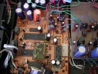
The CDP is a regular Magnavox CDB650 which was Pooged many years ago it has an SAA7210 decoder and SAA7220 Filter and a TDA1541A S1 DAC.
On the analog section had an AD846 (not shure, but it is a CFB opamp which was proposed originaly by Jung) keeping part of the original analog filter. Later I've been trying to replace it with an LM6181 CFB without any analog filtering.
The analog section PSU is using dedicated Jung/Sulzer super reg at (+)(-) 15V without the sensing option.
Hope I don't forget something important.
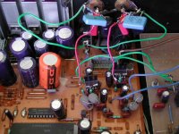
I just modified my Marantz CD-94 two days ago. I disconnected digital filter, so it's non oversampling now, changed and upgraded all electrolytics to Cerafine and HFQ, with ceramic bypasses at the pins. The output stage is using only first IC and I put OPA627 there in original config. Form output of OPA627, the signal goes directly to RCA jacks. I'm using 4.7 BG N for coupling, but I'm tempted to remove them. The resistors network at TDA1541 output was removed. It is still not finished yet (new clock and reclocker will be added, with new PS regulators) but as it is now, the sound is very good.
I appreciate your input Peter...
Since I am not satisfied with the CDP sound, been trying different approches to this I/V analog section but with my limited electronic knowledge I get frustrated, besides I don't get straight answers from the many well experianced guys around here such as say "you can't do that with an LM6181 so try this" or "your getting into deep waters so follow this approach." which has been the gereral attidude on DIYaudio forums.
Well, frustrated or not I continue to work on this CDP (at my slow pace). To beggin with, I'm quite amazed at all what it can be get from the TDA1541A, it's such an overwelming sound I get from the new opamp (minus the noise of course) that I will like to continue with original oversampling setup, for the moment.
One interesting thing with this "new" approach with the LM6181 is that I decoupled the chips rails with only one 1uf film cap very very near the pins which might be contributing to the excellent sound I'm getting.
On trying to solve the noise (thinking it could be PSU related) I tryed further decoupling adding a ceramic cap at each point plus a MKS 4 0.01u across both rails at the chip.
I had never before try to use ceramic caps, the regular types. The result after this addition degraded the sound.
Those are not regular ceramic caps and the way I'm doing it is described here: http://www.diyaudio.com/forums/showthread.php?s=&threadid=6232&highlight=mods+never+end
- Status
- This old topic is closed. If you want to reopen this topic, contact a moderator using the "Report Post" button.
- Home
- Source & Line
- Digital Line Level
- Simple I/V for TDA1541