Clocks & unwanted RF noise
Just another thought, while we're on the subject of clocks...
When I mounted the Trichord module in the Copland I took a look at what the +15v dc line looked like (ripple component). I had read the other night, that the clock board can send pulse effects back up the power supply lines to the power tap off point (and effectively pollute the supply to other ccts).
So, I took a look on the 'scope... don't ask me figures, but I saw the
ripple produced, and then wondered what the supply line would look like with the clock module disconnected from it - the result ? - the ripple vanished !
So, with that....I decided to connect up the clock module to an independent supply...namely, a 12v battery (outside the Copland's casework).
Now, when I looked at the same +15v supply line it had an INCREASED load of hash on it !!!
So, to my point :-
I don't seem to read anything within the posts around clocking devices about the possible RF that these devices are radiating into adjacent ccts within the CD player ...(?)
WADIA, on their website state that in their cd one-box designs, screen the digital and analogue sections (as well as power supply modules) from each other ...
Am I looking at things in an over-fussy way, or do you think it's good design sense to strive for this, as it seems that the clocking cct can add spurious rf hash into other ccts around the deck ?
Mind you, I did notice that Elso commented on the PI cct arrangement that stops any ripple going into and out over the power supply lines of his Kwack 7 design ...
(but this doesn't stop rf hash emanating from the cct though does it ?!?)
-Andy-
Just another thought,
while we're on the subject of clocks...When I mounted the Trichord module in the Copland I took a look at what the +15v dc line looked like (ripple component). I had read the other night, that the clock board can send pulse effects back up the power supply lines to the power tap off point (and effectively pollute the supply to other ccts).
So, I took a look on the 'scope... don't ask me figures, but I saw the
ripple produced, and then wondered what the supply line would look like with the clock module disconnected from it - the result ? - the ripple vanished !
So, with that....I decided to connect up the clock module to an independent supply...namely, a 12v battery (outside the Copland's casework).
Now, when I looked at the same +15v supply line it had an INCREASED load of hash on it !!!
So, to my point :-
I don't seem to read anything within the posts around clocking devices about the possible RF that these devices are radiating into adjacent ccts within the CD player ...(?)
WADIA, on their website state that in their cd one-box designs, screen the digital and analogue sections (as well as power supply modules) from each other ...
Am I looking at things in an over-fussy way, or do you think it's good design sense to strive for this, as it seems that the clocking cct can add spurious rf hash into other ccts around the deck ?
Mind you, I did notice that Elso commented on the PI cct arrangement that stops any ripple going into and out over the power supply lines of his Kwack 7 design ...
(but this doesn't stop rf hash emanating from the cct though does it ?!?)
-Andy-
Re: Changing taps
The theoretical advantage of linear interpolation is in increasing the effective sample rate to reduce the anti-image filter requirements. The disadvantage is HF roll-off and distortion. The NOS paradigm, in the extreme, calls for the elimination of all filters and that negates the only advantage offered by linear interpolation.
I used a spreadsheet to model different methods of interpolation and compared the shape of the plotted waveforms with those of straight NOS and a perfect sine wave. Linear interpolation was just one of dozens of things I tried and I was surprised to see it was not always the best.
I decided to pursue the matter further and designed a DAC that would allow me to actually hear, rather than just visualize, the differences. I also wrote software that did an exhaustive analysis of all the permutations of 16 DACs on 64 shift register taps at different frequencies to give me a starting place for listening tests.
Interpolation is inventing samples that were never recorded and there’s no reason those invented sample points have to be at even intervals. The idea is to recreate music and not be bound by a mathematical model that only applies to continuous, monochromatic sine waves.
When I was working with digital music synthesis, I learned that the synthesized music sounded more natural and less mechanical when random timing errors were introduced. Unpredictable variation is a natural part of acoustic music.
If the ideal is to have the analog output of the DAC change instantly at precisely the right time, then why is the TDA154x so popular? Look at the settling time specs. If a DAC takes 500ns to settle its output, it means the DAC is outputting the wrong value for 500ns. That being the case, who cares if the timing of the right value is off by a picosecond or two? I measured the TDA1543 and it sometimes took 5us for the analog output to settle. It must be the timing variations created by the unpredictable settling time that makes those DACs appeal to so many users.
The settling time of any particular DAC is a function of the step size. When the steps are small, so is the settling time. High sample-rate DACs settle faster than NOS DACs because the steps between the samples are smaller. Could that be a reason why upsampling and delta-sigma DACs sound unnatural to some people? And by all the accounts I’ve read, people who’ve heard the dCS Verona Master Clock with its dithered clock output say it sounds better than an undithered clock. Regardless of what they say about the evils of jitter, it appears many audiophiles prefer their digital music with a little added randomness.
-ecdesigns- said:So you either use the same time between samples or you don't. Using the same time between samples is already used in the octal D-I DAC. But perhaps I missed something.
Could you explain how you connected the tabs? and why?
The theoretical advantage of linear interpolation is in increasing the effective sample rate to reduce the anti-image filter requirements. The disadvantage is HF roll-off and distortion. The NOS paradigm, in the extreme, calls for the elimination of all filters and that negates the only advantage offered by linear interpolation.
I used a spreadsheet to model different methods of interpolation and compared the shape of the plotted waveforms with those of straight NOS and a perfect sine wave. Linear interpolation was just one of dozens of things I tried and I was surprised to see it was not always the best.
I decided to pursue the matter further and designed a DAC that would allow me to actually hear, rather than just visualize, the differences. I also wrote software that did an exhaustive analysis of all the permutations of 16 DACs on 64 shift register taps at different frequencies to give me a starting place for listening tests.
Interpolation is inventing samples that were never recorded and there’s no reason those invented sample points have to be at even intervals. The idea is to recreate music and not be bound by a mathematical model that only applies to continuous, monochromatic sine waves.
tubee said:On this way Ulas wants to try to keep up with the jitter produced in his own setup used.
When I was working with digital music synthesis, I learned that the synthesized music sounded more natural and less mechanical when random timing errors were introduced. Unpredictable variation is a natural part of acoustic music.
If the ideal is to have the analog output of the DAC change instantly at precisely the right time, then why is the TDA154x so popular? Look at the settling time specs. If a DAC takes 500ns to settle its output, it means the DAC is outputting the wrong value for 500ns. That being the case, who cares if the timing of the right value is off by a picosecond or two? I measured the TDA1543 and it sometimes took 5us for the analog output to settle. It must be the timing variations created by the unpredictable settling time that makes those DACs appeal to so many users.
The settling time of any particular DAC is a function of the step size. When the steps are small, so is the settling time. High sample-rate DACs settle faster than NOS DACs because the steps between the samples are smaller. Could that be a reason why upsampling and delta-sigma DACs sound unnatural to some people? And by all the accounts I’ve read, people who’ve heard the dCS Verona Master Clock with its dithered clock output say it sounds better than an undithered clock. Regardless of what they say about the evils of jitter, it appears many audiophiles prefer their digital music with a little added randomness.
Ulas: thanks for this convincing sounding explanaition of interpolation matters. With the phraze: "On this way Ulas wants to try to keep up with the jitter produced in his own setup used" I wanted to depict some critics because i had been reading another thread with lots of critics from you.
I am allready a long time busy with a 4 paralleled 1541 dac, done by 74/164 shift registers. I will see if will sound good, if not try something else. When pcb's are available, will try the D-I dac too eventually.
I modded a 304 mk2, this time kept the digital filter in. I must say now, dig. filtering is not that bad as a lot members still think it is. The PS, clock and I/V are very sensitive to mods.
I assume it is because it converts data with the multibit technique. (as PCM63, also a very good dac) Pro's: "warm" and natural sounding. Contra: some "roughness" in treble compared to delta/sigma or bitstream conversion.
I am allready a long time busy with a 4 paralleled 1541 dac, done by 74/164 shift registers. I will see if will sound good, if not try something else. When pcb's are available, will try the D-I dac too eventually.
I modded a 304 mk2, this time kept the digital filter in. I must say now, dig. filtering is not that bad as a lot members still think it is. The PS, clock and I/V are very sensitive to mods.
then why is the TDA154x so popular
I assume it is because it converts data with the multibit technique. (as PCM63, also a very good dac) Pro's: "warm" and natural sounding. Contra: some "roughness" in treble compared to delta/sigma or bitstream conversion.
Master clock injection
Hi NjoyTHEMUSIC,
thanks for your reply [post#541]
Best way is to use a separate (floating) power supply, like the battery you used, or a dedicated power supply. This saves a lot of problems.
Now , using above setup! connect the black wire (clock ground) to the ground connection were the 2 removed capacitors were soldered to. Connect the white wire (clock signal) to the Xtal input. Put a 100 Ohm termination resistor (SMD) between both clock ground and Xtal input to reduce jitter. Keep both clock wires as short as possible!
When you connected the Trichord to a floating external 12 V battery as you mentioned, where does (clock) ground go? If the Trichord is not connected to transport ground you get HF interference. That may have caused the increased loads of hash as you called it.
According to installation instructions, the black clock ground wire is not connected, so the HF clock return signal can start a interesting journy back trough lots of internal circuitry until it has finally reached Trichord ground. This is the case when connected directly to the internal power supply. There is hardly any other way since the Trichord power supply current musn't be allowed to run trough the transports clock circuitry. With a external floating power supply, power supply current can't flow trough the transport clock circuitry, and the black clock wire can be used as short clock return path.
I used a different approach, a very compact low current master clock module that can be located close to the clock injection point. The oscillator output and oscillator reference ground are connected to the transport using very short connections (< 0.5"). This way keeping the clock return path to reference ground very short. The Trichord, like many other clocks is way to big to use short connections. So the DAC internals may be radiated with HF noise.
No you are not looking at things in an over-fussy way, a external clock, installed the wrong way, can emit loads of HF interference and it is doubtful if sound quality will then still benefit from the clock upgrade. Remember most interference is caused by long clock wires / clock return paths.
You were thinking about the best point to inject the master clock, this becomes a bit fuzzy when clock wires that inject the master clock are that long. It only makes sence if master clock injection "wires" are very short.
Cheers,
John
John (ecdesigns) -
Thank you so much for your time & insight !!
I was begining to feel a bit guilty for interrupting the line of conversation on this link- I know you are all delving into more complex issues than what I'm faced with...
You've given me a lot to think about (and do)
Your help is greatly appreciated !
{Just wish I could buy you all a }
}
cheers for now !
-Andy-
Thank you so much for your time & insight !!
I was begining to feel a bit guilty for interrupting the line of conversation on this link- I know you are all delving into more complex issues than what I'm faced with...
You've given me a lot to think about (and do)
Your help is greatly appreciated !
{Just wish I could buy you all a
}cheers for now !
-Andy-
BCK "modulation" and sound quality
Hi Ulas,
Thanks for your interesting reply [post542]
Guess what happened yesterday, I tried to convert the sony format to match the octal D-I DAC. I delayed WS 7 BCK cycles and inverted it. I still used the philps format timing chain as I was experimenting. First sound impression was acually very good, despite using the wrong taps for the sony format.
I also have the impression that some "perfect" DAC's sound very dull and unnatural, that's also the reason I start building a NOS DAC years ago.
Problem is, sound can make a very good first impression. But when listening more carefully, especially during longer time periods, the gained sound quality sometimes isn't realistic and starts causing listening fatigue.
Then the jitter issue. I had some people come over to listen to the octal D-I DAC with differential I2S interface (2.5m cable was used). They said sound quality was natural and involving. After listening for some time, I wanted to play a track that was on the other CD changer, that one only had a SPDIF interface as it wasn't modified at that time. It also used a 2.5 meter SPDIF cable and a mini clock upgrade. After switching to SPDIF the beautiful sound was gone, the listeners urged me to use the other setup again.
After comparing both setups, the only difference was slightly larger jitter on the SPDIF interface. I didn't have reclocking at the DAC right then. Afterwards I added secondary reclocking (DAC side), at first sound quality seemed improved, now it's removed again, the beautiful sound is back.
So as before, there is something about BCK stability (playback timing parameters) that I can't pinpoint yet, perhaps it has something to do with errors introduced during sampling, or the sampling method itself. But the "correct" BCK timing makes a world of difference in sound quality, and little sense when trying to measure or explain it. There are many types of jitter (noise, specific repetitive waveform), one type could improve things, the other could degrade sound quality.
Perhaps a specifically type of low value jitter (FM modulation) is needed to get the perceived impression of natural sound quality. When simulating, did you take the "intermodulation effects" into account, that occur at higher frequencies, 21KHz oscillogram [post#100]. Perhaps this effect is "compensated" some how by the different timing chain taps you used.
BCK Timing seems to be the key issue here, and it seems to have far more effect than ultra low distortion, every DAC has it's specific "sound", maybe this is directly related to it's timing parameters. I tried other DAC's as well like the PCM1702, but sound quality was dissapointing, despite better specifications.
I think this is worth further investigation Ulas, very interesting!
I post a curious fact that occurred in my TDA1545 :
That thac works in a 4X oversampling japanese format if I am not wrong .
So I have been able to place a Tent Xo ( 8,4672Mhz) DIRECTLY to the BCK pin and back to the transport .
Some time after I decided to approach reclocking the WS lne : well the curious thing is that reclockin JUST WS -or- DATA line alone was producing massive distorsions to the sound .
Then I decided to reclock BOTH WS and DATA at the BCK (XO) reference ...
doing this by magic the soud stage opened - dynamics like I didnt heard before from that DAC and overall a relaxed playbeck and very focussed detail and perspective .
What I mean is that reclocking the WS and DATA line with 2 D flip flop in cascade to each line along with the Xo directly at the BCK has produced dramatic distorsion reduction in sound ... and hardly can hear a trace of jitter . So this is a case for investigation also since the *relation* between the 3 dac lines ( BCK DATA ws ) seems to be very important in the jitter reduction field . Of course that dramatic improvement couldnt be achieved without the use of a decent clock .
Hi ecdesigns!!
Thank you for sharing your knowledge with the rest of the world.
Your project has inspired me to hopefulley jump on...
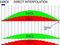
I have a theoretical question though... As seen on the attached pic that you sent a while ago, I notice a -- widening-- of the INTERPOLATED waveform. Trying to understand it, I used pen and paper to see what happens at the highest sampled frequency of 20KHZ, where there are only 2 available PCM-samples. Here The widening effect was much more pronounced due to the low number of "steps".
Could you please explain if this possibly is something to worry about ??
Thank you for sharing your knowledge with the rest of the world.
Your project has inspired me to hopefulley jump on...
I have a theoretical question though... As seen on the attached pic that you sent a while ago, I notice a -- widening-- of the INTERPOLATED waveform. Trying to understand it, I used pen and paper to see what happens at the highest sampled frequency of 20KHZ, where there are only 2 available PCM-samples. Here The widening effect was much more pronounced due to the low number of "steps".
Could you please explain if this possibly is something to worry about ??
Attachments
Serial data errors
Hi stefanobilliani,
Thanks for your reply [post#547]
The TDA1545A uses the japanese format, just like the TDA1543A. When only reclocking either DATA or WS, a significant delay is created for that signal only [post#532], especially with a low 8.4672 MHz master clock . This causes continuous data corruption as timing between master clock, DATA and WS is off. By reclocking both DATA and WS, timing is corrected, as both signals now have the same delay, and run fully synchronous with the master clock. If the sound quality has improved when compared to the first setup without reclocking, this puzzles me, as the TDA1545A is directly clocked from the masterclock.
There could have been jitter on both WS and DATA with respect to the master clock (one of them had jitter with respect to the other). This might have caused sporadical data corruption of single samples (data integrity is not fully 100%), causing some sample values to be wrong, but the majority of sample values to be right, this would not be interpreted as distortion, rather a degrading of sound quality. The DAC contains no corrective mechanism and just outputs the wrong sample values. This could also explain improvements achieved with reclocking. By exactly synchronizing BCK, DATA and WS. Timing errors are minimized. Even with a jittery master clock, (BCK), DATA and WS stay "locked" to the master clock and vary with it, keeping phase relations between them constant.
So even when the I2S signals are comming directly from the transport, sound quality can still benefit by reclocking them.
Linear Interpolation
Here is a plot that examines non-oversampling vs. linear oversampling vs. a sine wave.
The blue line is a 12KHz sine wave sampled at 1xFs. (Fs = 44.1KHz)
The green line is the same sine wave sampled at 1xFs with linear interpolation using 16 DACs.
The red line is the same sine wave sampled at 64xFs.
Here is the same plot with the addition of the area under the curve. The area indicates the amount of work done. You can also think of it as the volume of air moved by the speaker cone. The maximum displacement of the line in each half cycle is the total area under the curve for that period. In all cases the area under the linear interpolation curve is less than the other two meaning there is less energy transferred. E.g., high frequencies are rolled off.
Re: Serial data errors
Not so. The most that can be said is that the format of the TDA1545A encapsulates the format of the TDA1543A. In short the TDA1545A will work with data formatted specifically for the TDA1543A, but not the other way round.
The TDA1545A has no masterclock, just BCK, WS and DATA. The function of BCK is to load data into the dac. DATA is tied BCK and with a dac like the TDA1545A must be synchronous. Simply parachuting in another oscillator will cause the distortion referred to in post 547 due to asynchronicity between the source of the data and the added clock. The cascaded flip-flops force synchronize the data to the new clock.
-ecdesigns- said:Hi stefanobilliani,
Thanks for your reply [post#547]
The TDA1545A uses the japanese format, just like the TDA1543A.
Not so. The most that can be said is that the format of the TDA1545A encapsulates the format of the TDA1543A. In short the TDA1545A will work with data formatted specifically for the TDA1543A, but not the other way round.
When only reclocking either DATA or WS, a significant delay is created for that signal only [post#532], especially with a low 8.4672 MHz master clock . This causes continuous data corruption as timing between master clock, DATA and WS is off. By reclocking both DATA and WS, timing is corrected, as both signals now have the same delay, and run fully synchronous with the master clock. If the sound quality has improved when compared to the first setup without reclocking, this puzzles me, as the TDA1545A is directly clocked from the masterclock.
The TDA1545A has no masterclock, just BCK, WS and DATA. The function of BCK is to load data into the dac. DATA is tied BCK and with a dac like the TDA1545A must be synchronous. Simply parachuting in another oscillator will cause the distortion referred to in post 547 due to asynchronicity between the source of the data and the added clock. The cascaded flip-flops force synchronize the data to the new clock.
Ulas,
Good luck...
It is "NOS"... but it does oversample, just uses analog to do it that's all.
While it's busy not oversampling, It's generating new image frequencies, reinforcing old ones, and suppressing (mangling) highs in the audio band.
Analog linear interpolation is better that than FIR or IIR oversampling... just accept it.
I would like to see your graphs redone at 16 -18 kHz. Then, just for fun, subtract the linear-interpolated-oversampled final product from the original sine. Call this the "error signal" and show itsmagnitude overlayed.
Put a 100 Ohm termination resistor (SMD) between both clock ground and Xtal input to reduce jitter.
John -
One small point about this....when I implemented this step, I found the deck acted as though there was no clock feed (motor spinning up fast / laser mech not responding)
 . I then removed the 100 ohm smd resistor, and all returned to normal (???)
I placed the smd part on the servo control pcb (close to the IC where 'Xtal-in' is located) Have I mis-interpreted your info notes ?
thanks,
-Andy-
Re: Re: Serial data errors
Not really like that rfbrw :
in the case of the 1545A at 4 times oversampling it happens that BCK is the same as the transport clock and is 192 times fs = 8,4672Mhz.
So I am am talking of Synchronous operation . Infact the clock is fed simultaneously to the transport/processor and to the BCK of 1545A .
That works pretty good .
The fact is that reclocking both DATA and WS produce a better sound in terms of dinamics extension and of relaxed soundstage plus a very good perspective .
Having said that , the point of my post #547 was : reclocking *just* DATA or *just* WS separately- one at a time doesnt work ... or if you prefer ,works with massive audible distorsions. And this having the clock/BCK in sync with the transport/processor in this case .
Isnt it interesting to know why that is ???
This example is valid in the TDA 1545A and I am probably a litte off topic now
rfbrw said:
The TDA1545A has no masterclock, just BCK, WS and DATA. The function of BCK is to load data into the dac. DATA is tied BCK and with a dac like the TDA1545A must be synchronous. Simply parachuting in another oscillator will cause the distortion referred to in post 547 due to asynchronicity between the source of the data and the added clock. The cascaded flip-flops force synchronize the data to the new clock.
Not really like that rfbrw :
in the case of the 1545A at 4 times oversampling it happens that BCK is the same as the transport clock and is 192 times fs = 8,4672Mhz.
So I am am talking of Synchronous operation . Infact the clock is fed simultaneously to the transport/processor and to the BCK of 1545A .
That works pretty good .
The fact is that reclocking both DATA and WS produce a better sound in terms of dinamics extension and of relaxed soundstage plus a very good perspective .
Having said that , the point of my post #547 was : reclocking *just* DATA or *just* WS separately- one at a time doesnt work ... or if you prefer ,works with massive audible distorsions. And this having the clock/BCK in sync with the transport/processor in this case .
Isnt it interesting to know why that is ???
This example is valid in the TDA 1545A and I am probably a litte off topic now
Re: Re: Re: Serial data errors
BCK is not MCK. That you need a cascaded pair of flip-flops and that there is distortion without them should be enough to alert you to the fact that you were doing something wrong.
stefanobilliani said:
Not really like that rfbrw :
in the case of the 1545A at 4 times oversampling it happens that BCK is the same as the transport clock and is 192 times fs = 8,4672Mhz.
So I am am talking of Synchronous operation . Infact the clock is fed simultaneously to the transport/processor and to the BCK of 1545A .
That works pretty good .
The fact is that reclocking both DATA and WS produce a better sound in terms of dinamics extension and of relaxed soundstage plus a very good perspective .
Having said that , the point of my post #547 was : reclocking *just* DATA or *just* WS separately- one at a time doesnt work ... or if you prefer ,works with massive audible distorsions. And this having the clock/BCK in sync with the transport/processor in this case .
Isnt it interesting to know why that is ???
This example is valid in the TDA 1545A and I am probably a litte off topic now
BCK is not MCK. That you need a cascaded pair of flip-flops and that there is distortion without them should be enough to alert you to the fact that you were doing something wrong.
poobah said:Ulas,
Good luck...
It is "NOS"... but it does oversample, just uses analog to do it that's all.
While it's busy not oversampling, It's generating new image frequencies, reinforcing old ones, and suppressing (mangling) highs in the audio band.
Analog linear interpolation is better that than FIR or IIR oversampling... just accept it.
I would like to see your graphs redone at 16 -18 kHz. Then, just for fun, subtract the linear-interpolated-oversampled final product from the original sine. Call this the "error signal" and show itsmagnitude overlayed.
The amount of effort involved is reaching the point where one might as well start contemplating building a classical oversampling filter, audiophile fairy tales notwithstanding. The memory requirements of a 3-400 tap filter are not as large as I once thought and a filter based on splines would be interesting. Might even get a chance knock this Lanczos-3 thing that pops up from time to time in the Digital Drive on the head once and for all.
sounded more natural and less mechanical when random timing errors were introduced.
Ulas, what is your opinion about selection grades, single crown, double crown? good, no good?
Re: Re: Re: Re: Serial data errors
Believe it or not I can assure you that in the CD723 BCK = MCK(or transport clock or whatelse you wnt to call it )
The dac works perfectly without 2 pairs of cascade Dflip flops .
I cant see where is the point in misreading posts ...
I end up thinking that probably the D Flip Flop introduces too much delay if used just in one line .... that probably is what causes distorsions ....
Thanks
rfbrw said:
BCK is not MCK. That you need a cascaded pair of flip-flops and that there is distortion without them should be enough to alert you to the fact that you were doing something wrong.
Believe it or not I can assure you that in the CD723 BCK = MCK(or transport clock or whatelse you wnt to call it )
The dac works perfectly without 2 pairs of cascade Dflip flops .
I cant see where is the point in misreading posts ...
I end up thinking that probably the D Flip Flop introduces too much delay if used just in one line .... that probably is what causes distorsions ....
Thanks
rfbrw wrote:
Since it is not your effort...
The amount of effort involved is reaching the point...
Since it is not your effort...
- Home
- Source & Line
- Digital Line Level
- Building the ultimate NOS DAC using TDA1541A