Okay then, rfbrw, I know you can't be bothered to 'teach us a lesson', but purely in the interests of spreading knowledge and understanding (think of it so that we all become somewhat wiser and run less risk of frustrating you), could you explain how a DAC output behaves?Tiime was when I would have felt obliged to the show you two the error of your ways as others have done for me for no other reason than they were able to but these days I can't be bothered.
Having done this stuff professionally, I'd like to think I have some idea of what I am doing but if you two think you are right and I am wrong, good luck to you.
Now, when I studied this for my electronics degree (which I have used professionally ever since) about ten years ago, I was of the understanding that once a digital value has been latched into its input, after some settling time, the analogue output is held at a particular level that represents the input digital symbol.
This output level is present and (ideally) doesn't change until the next symbol is latched for that channel (i.e. for approximately the sample period, minus settling time).
With this 'staircase output', it is regarded the job of the output antialias filter to remove the aliasing higher frequencies present, and essentially smooth this out. I can't remember the name, but there is an ideal impulse response that a filter can have that will allow a perfect sine to be reproduced with just two sample points (i.e. a 22kHz sinewave).
What part of that have I misunderstood? Its very possible, so please tell me.
And besides, I wasn't in anyway disproving you, I was specifying what I believed to be the case, in my opinion.
Getting angry with others because they have different knowledge and opinions doesn't help anyone, especially yourself.
Regards,
Phil
P.S. And I really do envy you if you have time to build stuff. I've got loads I want to build!
Re: 2 sample response
Interesting riposte, EC but overlap is simply impossible.
Each dac is triggered after WS
It makes no difference which DAC it is, they are all separated by 8 BCK cycles. When DAC1 is triggered by the relevant WS signal DAC's 2 to 8 are still loading their internal serial to parallel registers with data. DAC2 won't trigger for another 8 BCK cycles and when it does, DAC1 will already have started loading the left channel data of the the next sample and DAC's 3 to 8 will still be loading the current sample.
The whole point of this technique, and it dates back to the the 80's where CD is concerned, is to trade physical resources for dac performance. One creates a composite dac out of 8 dacs that performs as though it were a single dac running at a 352K8 sample rate, something a single TDA1541A can do but thats another story.
Interesting riposte, EC but overlap is simply impossible.
Each dac is triggered after WS
An externally hosted image should be here but it was not working when we last tested it.
It makes no difference which DAC it is, they are all separated by 8 BCK cycles. When DAC1 is triggered by the relevant WS signal DAC's 2 to 8 are still loading their internal serial to parallel registers with data. DAC2 won't trigger for another 8 BCK cycles and when it does, DAC1 will already have started loading the left channel data of the the next sample and DAC's 3 to 8 will still be loading the current sample.
The whole point of this technique, and it dates back to the the 80's where CD is concerned, is to trade physical resources for dac performance. One creates a composite dac out of 8 dacs that performs as though it were a single dac running at a 352K8 sample rate, something a single TDA1541A can do but thats another story.
Hi rfbrw,
Thanks for the response.
I know that seemed like hassle to you, but that was really useful for me. This is definitely something I want to look into now.
I hadn't assumed that a DAC would do this. Like I said, I was aware of some settling time, but I didn't realise it was for half the sample period.
What happens at the output of the DAC when this is occurring (i.e. for the other 8BCLK cycles? Surely this can be seen with an oscilloscope?
I'm amazed that these DACs can provide a decent signal at all.
Cheers,
Phil
Overlap impossible?
Hi frbrw,
Thanks for your reply [post#422]
I will try to explain the operation of the octal D-I DAC in more detail, as this might also be very interesting for other readers.
> If overlap would simply be impossible, there would be no resolution enhancement and no higher maximum amplitude from the 8 DAC's . I already posted some oscillograms earlier as "evidence"
 ") .
.
If the TDA1541A would output it's sample only during 32BCK, you probably end up with a squarewave signal when 1 DAC is used , as 32BCK gaps would occur when the DAC outputs are zero volts or in tri state?
If I am correct, the TDA1541A outputs its sample after the negative going edge of WS and the following positive going edge of BCK plus a typical 500nS delay. The output sample remains there (TDA1541A internal L and R output latch as indicated in the Philips datasheet) until the next negative going edge of WS plus 0.5 BCK delay, so the sample REMAINS on the output during full 64BCK cycles. During this time, the next sample is already clocked in and is stored in the input latch, and it can take full 64BCK cycles to shift in both L + R channel samples.
Timing chain delays always stay WITHIN this 64BCK window. Max. delay time (DAC6) is 56BCK, so this is still within the 64BCK window.
When DAC1 starts outputting sample n, 8 BCK later DAC5 has also completed loading the same sample n and outputs it, as DAC 5 received the complete bitstream only 8 BCK cycles later [post#414], and in fact is loading it's bitstream together with DAC 1. Similar happens with DAC3,7,2,8,4,6 in that sequence. Remember, the shift register delay circuit delays the entire bitstream, all individual databits included, so it also acts as a serial sample BUFFER / memory. Same applies for WS (very important), it is not just delayed, it is serially buffered by the serial shiftregister and remains fully in sync with both BCK and the delayed data. So the D-I system needs serial memory to function correctly.
That is why I call the samples from DAC's 5,3,7,2,8,4,6 clone samples, as they are merely exact copies of DAC1, spread out within 64BCK cycles, at 8BCK intervals.
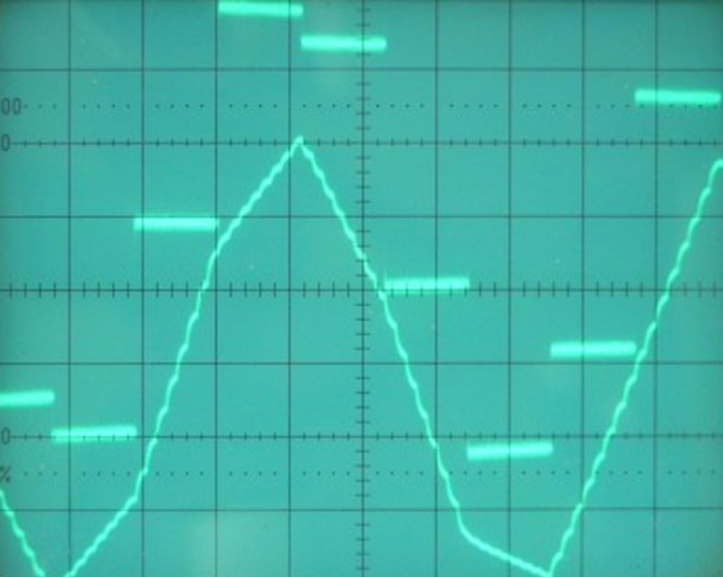
All 8 DAC's are clocking in the same bitstream of sample n, the only difference is, they complete this operation at multiples of 8BCK in this case. So all 8 DAC's can output sample n in a way that causes a partially overlap of sample n. This can be verified by the higer maximum output voltage, as this increases with the amount of DAC's used. If there was no overlap, the maximum output voltage had to remain the same and there would be no resolution increase. Resolution increase of both amplitude and virtual sample rate can only be obtained by partial overlap. During the output of the combined sample, part of samples n-1 and n+1 are also added to the output as illustrated in dip1.jpg [post#414]. So 3 sequential (new) samples are being interpolated within the combined sample.
If a similar result needs to be created with only one 20 or 24 bit DAC, there is no other way but increasing BCK rate by 8. Interpolated values have to be calculated and temporarily stored for both L and R channels, these values then have to be placed in the serial bitstream. This would be much more complicated, I love to see a circuit diagram of this.
Maybe this octal D-I DAC system isn't that bad after all, considering this alternative.
Hi frbrw,
Thanks for your reply [post#422]
I will try to explain the operation of the octal D-I DAC in more detail, as this might also be very interesting for other readers.
> If overlap would simply be impossible, there would be no resolution enhancement and no higher maximum amplitude from the 8 DAC's
. I already posted some oscillograms earlier as "evidence" . If the TDA1541A would output it's sample only during 32BCK, you probably end up with a squarewave signal when 1 DAC is used , as 32BCK gaps would occur when the DAC outputs are zero volts or in tri state?
If I am correct, the TDA1541A outputs its sample after the negative going edge of WS and the following positive going edge of BCK plus a typical 500nS delay. The output sample remains there (TDA1541A internal L and R output latch as indicated in the Philips datasheet) until the next negative going edge of WS plus 0.5 BCK delay, so the sample REMAINS on the output during full 64BCK cycles. During this time, the next sample is already clocked in and is stored in the input latch, and it can take full 64BCK cycles to shift in both L + R channel samples.
Timing chain delays always stay WITHIN this 64BCK window. Max. delay time (DAC6) is 56BCK, so this is still within the 64BCK window.
When DAC1 starts outputting sample n, 8 BCK later DAC5 has also completed loading the same sample n and outputs it, as DAC 5 received the complete bitstream only 8 BCK cycles later [post#414], and in fact is loading it's bitstream together with DAC 1. Similar happens with DAC3,7,2,8,4,6 in that sequence. Remember, the shift register delay circuit delays the entire bitstream, all individual databits included, so it also acts as a serial sample BUFFER / memory. Same applies for WS (very important), it is not just delayed, it is serially buffered by the serial shiftregister and remains fully in sync with both BCK and the delayed data. So the D-I system needs serial memory to function correctly.
That is why I call the samples from DAC's 5,3,7,2,8,4,6 clone samples, as they are merely exact copies of DAC1, spread out within 64BCK cycles, at 8BCK intervals.
All 8 DAC's are clocking in the same bitstream of sample n, the only difference is, they complete this operation at multiples of 8BCK in this case. So all 8 DAC's can output sample n in a way that causes a partially overlap of sample n. This can be verified by the higer maximum output voltage, as this increases with the amount of DAC's used. If there was no overlap, the maximum output voltage had to remain the same and there would be no resolution increase. Resolution increase of both amplitude and virtual sample rate can only be obtained by partial overlap. During the output of the combined sample, part of samples n-1 and n+1 are also added to the output as illustrated in dip1.jpg [post#414]. So 3 sequential (new) samples are being interpolated within the combined sample.
If a similar result needs to be created with only one 20 or 24 bit DAC, there is no other way but increasing BCK rate by 8. Interpolated values have to be calculated and temporarily stored for both L and R channels, these values then have to be placed in the serial bitstream. This would be much more complicated, I love to see a circuit diagram of this
.Maybe this octal D-I DAC system isn't that bad after all, considering this alternative.
Re: Overlap impossible?
Will this work with TDA 1543 ?
I am listening to a double combination (2 tda 1543) with dac 2 at WS32 and Data32 not balanced .
Output stage : Pass D1 (modified ) with jfets .
-ecdesigns- said:Hi frbrw,
Thanks for your reply [post#422]
I will try to explain the operation of the octal D-I DAC in more detail, as this might also be very interesting for other readers.
> If overlap would simply be impossible, there would be no resolution enhancement and no higher maximum amplitude from the 8 DAC's
If the TDA1541A would output it's sample only during 32BCK, you probably end up with a squarewave signal when 1 DAC is used , as 32BCK gaps would occur when the DAC outputs are zero volts or in tri state?
If I am correct, the TDA1541A outputs its sample after the negative going edge of WS and the following positive going edge of BCK plus a typical 500nS delay. The output sample remains there (TDA1541A internal L and R output latch as indicated in the Philips datasheet) until the next negative going edge of WS plus 0.5 BCK delay, so the sample REMAINS on the output during full 64BCK cycles. During this time, the next sample is already clocked in and is stored in the input latch, and it can take full 64BCK cycles to shift in both L + R channel samples.
Timing chain delays always stay WITHIN this 64BCK window. Max. delay time (DAC6) is 56BCK, so this is still within the 64BCK window.
When DAC1 starts outputting sample n, 8 BCK later DAC5 has also completed loading the same sample n and outputs it, as DAC 5 received the complete bitstream only 8 BCK cycles later [post#414], and in fact is loading it's bitstream together with DAC 1. Similar happens with DAC3,7,2,8,4,6 in that sequence. Remember, the shift register delay circuit delays the entire bitstream, all individual databits included, so it also acts as a serial sample BUFFER / memory. Same applies for WS (very important), it is not just delayed, it is serially buffered by the serial shiftregister and remains fully in sync with both BCK and the delayed data. So the D-I system needs serial memory to function correctly.
That is why I call the samples from DAC's 5,3,7,2,8,4,6 clone samples, as they are merely exact copies of DAC1, spread out within 64BCK cycles, at 8BCK intervals.
All 8 DAC's are clocking in the same bitstream of sample n, the only difference is, they complete this operation at multiples of 8BCK in this case. So all 8 DAC's can output sample n in a way that causes a partially overlap of sample n. This can be verified by the higer maximum output voltage, as this increases with the amount of DAC's used. If there was no overlap, the maximum output voltage had to remain the same and there would be no resolution increase. Resolution increase of both amplitude and virtual sample rate can only be obtained by partial overlap. During the output of the combined sample, part of samples n-1 and n+1 are also added to the output as illustrated in dip1.jpg [post#414]. So 3 sequential (new) samples are being interpolated within the combined sample.
If a similar result needs to be created with only one 20 or 24 bit DAC, there is no other way but increasing BCK rate by 8. Interpolated values have to be calculated and temporarily stored for both L and R channels, these values then have to be placed in the serial bitstream. This would be much more complicated, I love to see a circuit diagram of this
Maybe this octal D-I DAC system isn't that bad after all, considering this alternative.
Will this work with TDA 1543 ?
I am listening to a double combination (2 tda 1543) with dac 2 at WS32 and Data32 not balanced .
Output stage : Pass D1 (modified ) with jfets .
Very simple proof that it is tue what I posted in post #404
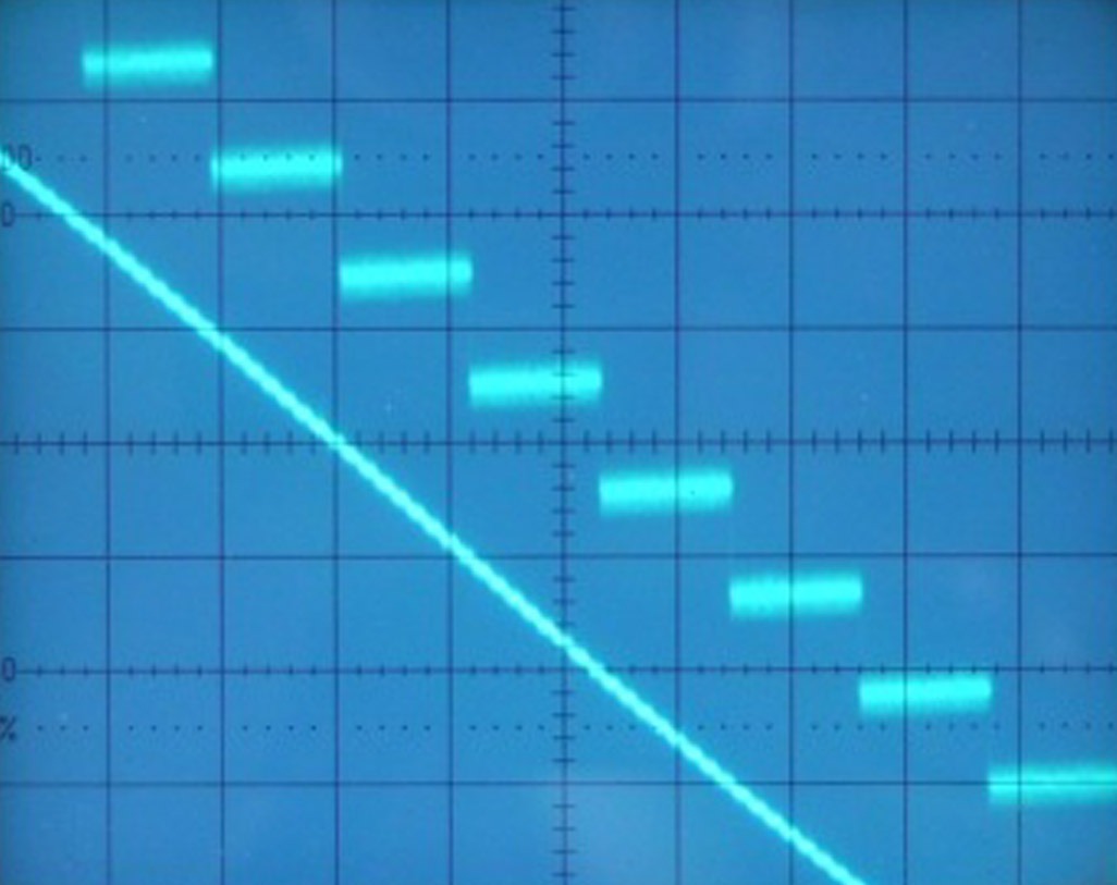
1 DAC carries current of new sample & 7 DACs carry current of previous sample -> 2 DACs carry current of new sample & 6 DACs carry current of previous sample -> 3 DACs carry current of new sample & 5 DACs carry current of previous sample -> 4 DACs carry current of new sample & 4 DACs carry current of previous sample -> 5 DACs carry current of new sample & 3 DACs carry current of previous sample -> 6 DACs carry current of new sample & 2 DACs carry current of previous sample -> 7 DACs carry current of new sample & 1 DAC carries current of previous sample -> 8 DACs carry current of new sample & 0 DACs carry current of previous sample -> starts next original sample...
Blown up pics of what EC posted.
Clearly one non-os step is transformed to eight steps.
This is only possible if after first DAC "0", all DACs "n" are delayed by n/8 sampling period with n = 1 to 7
EC, look closely at your own diagram from post 420. The series of short arcs run end to end. Yes the sample remains for the entire sample time but the effect of linear interpolation is to create a composite dac that runs 8 times faster. The sample time for the composite dac is 2.84 us or 8 cycles. You have to look at it as a single dac.
An externally hosted image should be here but it was not working when we last tested it.
Here is a very cheap TDA1541A on ebay.
But don't forget to look on the shipping cost.
http://cgi.ebay.ca/Philips-TDA1541A...9QQihZ013QQcategoryZ36332QQrdZ1QQcmdZViewItem
But don't forget to look on the shipping cost.
http://cgi.ebay.ca/Philips-TDA1541A...9QQihZ013QQcategoryZ36332QQrdZ1QQcmdZViewItem
Using other DAC chips
Hi, stefanobilliani
Thanks for your reply [post#425]
> Yes it will work with a TDA1543, TDA1545 or a similar 16 bit 2 channel DAC. By using 2 DAC chips both resolution and virtual sample rate is only doubled. Output currents can be added similar to the TDA1541A.
TDA1541A: 4 mA full scale current, 0.001 distortion
TDA1545: 1 mA full scale current, 0.004% distortion
TDA1543: 2.3 mA full scale current, 0.018% distortion
(Typical values)
I added a overview of the number of DAC's used and the effect on resolution
2 DAC's, 17 bit, 88.2 KHz virtual sample rate, 2 steps, 32BCK sample
4 DAC's, 18 bit, 176.4 KHz virtual sample rate, 4 steps, 16BCK sample
8 DAC's, 19 bit, 352.8 KHz virtual sample rate, 8 steps, 8BCK sample
16 DAC's, 20 bit, 705.4 KHz virtual sample rate, 16 steps, 4BCK sample
32 DAC's, 21 bit, 1.4112 MHz virtual sample rate, 32 steps, 2BCK sample
Note number of bits is theoretical and depends on DAC chip specifications.
Re: Overlap impossible?
None of the above would be necessary. DSP theory states that each doubling of the sample rate is equivalent to adding one bit to the word. For example, the 14bit 176K4 combination of the SAA7030 and the TDA1540 is meant to yield the same performance as the 16 bit TDA1541 on its own.
If I increased the wordlength through solely hardware means, easily done, btw, Crystal have an application note on it, I would not need the higher sample rate.
-ecdesigns- said:
If a similar result needs to be created with only one 20 or 24 bit DAC, there is no other way but increasing BCK rate by 8. Interpolated values have to be calculated and temporarily stored for both L and R channels, these values then have to be placed in the serial bitstream. This would be much more complicated, I love to see a circuit diagram of this
None of the above would be necessary. DSP theory states that each doubling of the sample rate is equivalent to adding one bit to the word. For example, the 14bit 176K4 combination of the SAA7030 and the TDA1540 is meant to yield the same performance as the 16 bit TDA1541 on its own.
If I increased the wordlength through solely hardware means, easily done, btw, Crystal have an application note on it, I would not need the higher sample rate.
Found this: http://www.tnt-audio.com/sorgenti/trinity_tech_e.html
In short:
- arrangement is further 8x oversampling
- "sort of oversampling" with a fancy name.
Looks similar to this (?), just that the dig filter is still there.
But with a pricetag of >40k euro (yes 40000) it will be hard to find one for reverse engineering.
In short:
- arrangement is further 8x oversampling
- "sort of oversampling" with a fancy name.
Looks similar to this (?), just that the dig filter is still there.
But with a pricetag of >40k euro (yes 40000) it will be hard to find one for reverse engineering.
Dear Bernhard,
How can we detect a fake DAC?
Thanks.
M
Here is a very cheap TDA1541A on ebay.
How can we detect a fake DAC?
Thanks.
M
Hi Max,
The subject of fake TDA1541A versions has been extensively discussed on other threads. You can do a search if you like, but when it comes down to it, it is unlikely that anyone will try to go through the hassel of making a fake TDA1541A since it is "cheap" (~$12) to begin with compared to the S1 (single crown) or S2 (double crown). Some fake "S2" are obvious with different color or smudged crown signiture on the chip, but some are difficult to tell. Members on this board who have both plain and S2 versions say there is an obvious sonic difference when you replace one chip over the other in the same DAC. But I don't know of any measurement that can verify the authenticity of which version you have. Seems the the prevailing wisdom is not to get any S1 or S2 from China because the market over there is flooded with fake chips. Hope this helps.
The subject of fake TDA1541A versions has been extensively discussed on other threads. You can do a search if you like, but when it comes down to it, it is unlikely that anyone will try to go through the hassel of making a fake TDA1541A since it is "cheap" (~$12) to begin with compared to the S1 (single crown) or S2 (double crown). Some fake "S2" are obvious with different color or smudged crown signiture on the chip, but some are difficult to tell. Members on this board who have both plain and S2 versions say there is an obvious sonic difference when you replace one chip over the other in the same DAC. But I don't know of any measurement that can verify the authenticity of which version you have. Seems the the prevailing wisdom is not to get any S1 or S2 from China because the market over there is flooded with fake chips. Hope this helps.
Many thanks, MGH.
Sorry. I didn't realize that.
M
The subject of fake TDA1541A versions has been extensively discussed on other threads.
Sorry. I didn't realize that.
M
Hi rfbrw,
thanks for your reply [post#427]
So the octal D-I DAC can be compared with a single 19 bit DAC running at 352.8KHz sample rate. The higher sample frequency is obtained by adding delayed samples, resulting in frequency multiplication by 8. The linear interpolation is soly obtained by sequential adding/subtracting of DAC output currents, resulting in a higher resolution. Temporary storage of samples (memory) during generation of time delays is done in the serial shift register.
So the main advantage of the octal D-I DAC is obtaining a output signal similar to a 8X oversampling DAC (resolution and sample rate) without being one, as no digital interpolation filter or higher BCK clock frequency are used. This results in a excellent phase linearity over the entire audio range.
The overlap is important to know for both noise reduction and averaging linearity errors. I haven't calculated the exact average overlap factor yet but it must be around 50% according to the attenuation needed. With 50% average overlap, the octal D-I DAC should have similar noise reduction and linearity error averaging as 4 DAC's operating in parallell.
post[#431]
When the word length would be increased by hardware, and 44.1KHz sample rate would be used, you end up with a higer resolution DAC running at 44.1KHz. When you look at the oscillogram [post#426], what would happen in this case? you end up with a course step pattern similar to the single NOS-DAC. You need to increase the sample rate too for obtaining higher resolution like the oscillogram of the octal D-I DAC shows.
So when using a single 19 bit DAC, somehow the sample rate has to be increased (oversampling), when this is done, you also need a digital interpolation filter to generate the added samples. This is even the case when using a sample rate converter like the AD1895.
GTE trinity DAC
Hi Guido,
Thanks for your reply [post#432]
Very interesting,
The article doesn't have enough details on how the 16 DAC's are controlled on the digital side. But it still uses a selectable DF1706 / SM5847 digital interpolation filter. The 16 DAC's seem to be arranged similar to the octal D-I DAC, increasing resolution. So this GTE Trinity DAC is a standard oversampling DAC, that doesn't need a analog corrective output filter due to resolution enhancement using 16 DAC's. It seems as if the digital filters are not used (bypassed) at higher input sampling rates (192KHz), but I am not sure of that.
The main difference with the octal D-I DAC is the presence of a digital interpolation filter (the one I just tried to avoid), the absence of the harmonic balancing tube output stage and a more complex and critical setup. You already mentioned the slightly higher price.
If DIYaudio members are interested, I can post a schematic diagram of a timing chain that can drive 2...32 DAC's. 32 DAC's could generate a theoretical resolution of 21 bits at 1.4112 MHz virtual sample rate.
But with the provided information in this thread, one could build a DAC similar to the GTE trinity DAC by adding a digital interpolation filter (2X, 4X or 8X) between the audio receiver and the octal D-I DAC analog mainboard. Even DIYaudio members who don't like NOS-DAC's can experiment with this setup. The advantage is, they can leave out the analog corrective output filter due to the very high (virtual) sample rate. With a 8X interpolation filter or sample rate converter, a virtual sample rate of 2.82 MHz could be achieved.
Re: GTE trinity DAC
Do they use 16 x 1704 per channel ? Multiply 32 with the cost of a 1704. Also they claim to select the chips themselves...
If I was a big high end manufacturer of DACs,
I would order tens of thousands of 1704s,
build one setup that allows for testing SMDs without soldering,
( as a very good customer ) have a deal with TI that allows me to return those 95% of unsoldered chips that have failed in my tests back to TI or the distributor who will sell them to the clueless DIYers
Or send to them as samples
-ecdesigns- said:The main difference with the octal D-I DAC is the presence of a digital interpolation filter (the one I just tried to avoid), the absence of the harmonic balancing tube output stage and a more complex and critical setup. You already mentioned the slightly higher price.
Do they use 16 x 1704 per channel ? Multiply 32 with the cost of a 1704. Also they claim to select the chips themselves...
If I was a big high end manufacturer of DACs,
I would order tens of thousands of 1704s,
build one setup that allows for testing SMDs without soldering,
( as a very good customer ) have a deal with TI that allows me to return those 95% of unsoldered chips that have failed in my tests back to TI or the distributor who will sell them to the clueless DIYers
Or send to them as samples
- Home
- Source & Line
- Digital Line Level
- Building the ultimate NOS DAC using TDA1541A