Hi maxlorenz,
No, I'm not angry") [post#375]
[post#375]
I just wanted to indicate the errors produced by NOS-DAC's and the octal D-I DAC are present, but wanted to put them into perspective. By over-emphasizing problems there is no point in designing anything as nothing will ever be perfect enough. One theory fill follow the other, with the end result a NO-DAC.
I will take your wise advice,
As far as I am concerned, the octal D-I DAC also transmits the soul of music. In my humble opinion this is mainly caused by both phase linearity and harmonic balancing using the mixed mode. The Direct Interpolation reduces harmonics amplitude when compared to the standard NOS-DAC. I already invited one DIYaudio member for a listening session.
Resting from time to time is very difficult for me, I have been working for over 15 years now without a holliday. Guess that makes me kind of a workaholic.
No, I'm not angry
[post#375]I just wanted to indicate the errors produced by NOS-DAC's and the octal D-I DAC are present, but wanted to put them into perspective. By over-emphasizing problems there is no point in designing anything as nothing will ever be perfect enough. One theory fill follow the other, with the end result a NO-DAC.
I will take your wise advice,
As far as I am concerned, the octal D-I DAC also transmits the soul of music. In my humble opinion this is mainly caused by both phase linearity and harmonic balancing using the mixed mode. The Direct Interpolation reduces harmonics amplitude when compared to the standard NOS-DAC. I already invited one DIYaudio member for a listening session.
Resting from time to time is very difficult for me, I have been working for over 15 years now without a holliday. Guess that makes me kind of a workaholic
.Some octal D-I DAC oscillograms
Hi all,
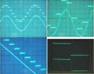
I added some oscillograms that show comparison between signals generated by a standard NOS-DAC and octal D-I DAC, both DAC's get the same SPDIF input signal, this might put things in perspective. Oscillograms also show both DAC output signals run nicely in phase.
Photo top left, shows how the octal D-I DAC smoothes a course stepped sinewave
Photo top right, shows what is still recovered with very few steps.
Photo bottom left, shows a 500Hz sinewave greatly magnified, notice the gained resolution
Photo bottom right, shows a 1 KHz squarewave, notice the flat responce and the steps on the transient
So the squarewave shaped signals with mainly odd harmonics, are converted to a more sawtooth / triangle shaped signal with more even harmonics. Soundwise even harmonic distortion has a less negative effect on sound quality then odd harmonic distortion.
The major harmonics are caused by the difference between a pure sinewave and the stepped approximation. The harmonics amplitude is in relation with the amplitude of the error signal. By generating smoother stepped sinewave signals, the amplitude of the error signal drops accordingly. The harmonics are still there, but their amplitude has been lowered. By the higher virtual sample frequency, harmonics are shifted up the spectrum, so interference in the audio spectrum is reduced
One could use a (Bessel) filter to attenuate these residual harmonics, if desired, they are already attenuated by bandwith limiting in the amplifier
Hi all,
I added some oscillograms that show comparison between signals generated by a standard NOS-DAC and octal D-I DAC, both DAC's get the same SPDIF input signal, this might put things in perspective. Oscillograms also show both DAC output signals run nicely in phase.
Photo top left, shows how the octal D-I DAC smoothes a course stepped sinewave
Photo top right, shows what is still recovered with very few steps.
Photo bottom left, shows a 500Hz sinewave greatly magnified, notice the gained resolution
Photo bottom right, shows a 1 KHz squarewave, notice the flat responce and the steps on the transient
So the squarewave shaped signals with mainly odd harmonics, are converted to a more sawtooth / triangle shaped signal with more even harmonics. Soundwise even harmonic distortion has a less negative effect on sound quality then odd harmonic distortion.
The major harmonics are caused by the difference between a pure sinewave and the stepped approximation. The harmonics amplitude is in relation with the amplitude of the error signal. By generating smoother stepped sinewave signals, the amplitude of the error signal drops accordingly. The harmonics are still there, but their amplitude has been lowered. By the higher virtual sample frequency, harmonics are shifted up the spectrum, so interference in the audio spectrum is reduced
One could use a (Bessel) filter to attenuate these residual harmonics, if desired, they are already attenuated by bandwith limiting in the amplifier
Attachments
poobah said:I
the graph would not post here well.
Do you think it would hurt anybody ?
About the possible reduction of nonlinearity:
I did not look at the schematics but if it is linear interpolation of 8 DACs, it should be at the start of a new original sample:
1 DAC carries current of new sample & 7 DACs carry current of previous sample -> 2 DACs carry current of new sample & 6 DACs carry current of previous sample -> 3 DACs carry current of new sample & 5 DACs carry current of previous sample -> 4 DACs carry current of new sample & 4 DACs carry current of previous sample -> 5 DACs carry current of new sample & 3 DACs carry current of previous sample -> 6 DACs carry current of new sample & 2 DACs carry current of previous sample -> 7 DACs carry current of new sample & 1 DAC carries current of previous sample -> 8 DACs carry current of new sample & 0 DACs carry current of previous sample -> starts next original sample...
So there are 8 different combinations of paralleled DACs inside one original sample.
That could be even more beneficial than just paralleling.
Please correct me if I'm wrong.
rfbrw said:
...we don't want no no-sayers here in town.
And no clueless photographers either.
Nice to hear that you share my opinion about the notorious no-sayers
Any clueless photographers around ?
Bernhard said:About the possible reduction of nonlinearity:
I did not look at the schematics but if it is linear interpolation of 8 DACs, it should be at the start of a new original sample:
1 DAC carries current of new sample & 7 DACs carry current of previous sample -> 2 DACs carry current of new sample & 6 DACs carry current of previous sample -> 3 DACs carry current of new sample & 5 DACs carry current of previous sample -> 4 DACs carry current of new sample & 4 DACs carry current of previous sample -> 5 DACs carry current of new sample & 3 DACs carry current of previous sample -> 6 DACs carry current of new sample & 2 DACs carry current of previous sample -> 7 DACs carry current of new sample & 1 DAC carries current of previous sample -> 8 DACs carry current of new sample & 0 DACs carry current of previous sample -> starts next original sample...
So there are 8 different combinations of paralleled DACs inside one original sample.
That could be even more beneficial than just paralleling.
Please correct me if I'm wrong.
You are wrong. All samples are 'original' and nothing is in parallel.
Bernhard said:
Nice to hear that you share my opinion about the notorious no-sayers
Can't say I do, not that it matters much. You'll talk a lot and measure a lot but it will be a cold day in hell when you actually make anything.
rfbrw said:
You are wrong. All samples are 'original' and nothing is in parallel.
Ok, samples are original, but only on the digital side.
The DACs get them with different delays.
The delays are < one sample so the samples overlap and that is where the DACs are parallel.
On the analog side x DAC-currents from a previous sample are added to y DAC-currents from the next sample, and the I/V does see it as a new & wrong sample.
Your post #408 is not worth a reply.
I agree with Bernhard, a DACs output is held until the next sample value is reproduced. So all the DAC outputs, at any given time, will be providing a current - so they are all summed as they are connected in parallel.
rfbrw, I think you are unreasonable to comment like you did. I am incredibly distracted, and I rarely make much kit at the moment. Everybody's commitments and distractions elsewhere in life impact this. I envy you as you obviously have more time than I (and perhaps Bernhard) to craft things. However, there is nothing wrong at all with theoretical discussion, and sensible measurement. They have their places.
This is a great thread. Please, lets not spoil it!
Cheers,
Phil
Bernhard said:
Ok, samples are original, but only on the digital side.
The DACs get them with different delays.
The delays are < one sample so the samples overlap and that is where the DACs are parallel.
On the analog side x DAC-currents from a previous sample are added to y DAC-currents from the next sample, and the I/V does see it as a new & wrong sample.
philpoole said:I agree with Bernhard, a DACs output is held until the next sample value is reproduced. So all the DAC outputs, at any given time, will be providing a current - so they are all summed as they are connected in parallel.
Tiime was when I would have felt obliged to the show you two the error of your ways as others have done for me for no other reason than they were able to but these days I can't be bothered.
Having done this stuff professionally, I'd like to think I have some idea of what I am doing but if you two think you are right and I am wrong, good luck to you.
rfbrw, I think you are unreasonable to comment like you did. I am incredibly distracted, and I rarely make much kit at the moment. Everybody's commitments and distractions elsewhere in life impact this. I envy you as you obviously have more time than I (and perhaps Bernhard) to craft things. However, there is nothing wrong at all with theoretical discussion, and sensible measurement. They have their places.
Perhaps next time, before parachuting in, you would seek to make yourself aware of the history involved.
Dear Ecdesigns:
I feel honoured you even take the time to answer my "supporting" post.
I know. You are very patient!
Sometimes I wish I could be here, to avoid thread's contamination.
Solid technichal advices are good for the thread's progresion but "bad vibrations" replies are better avoided, gentlemen.

Good luck
M
I feel honoured you even take the time to answer my "supporting" post.
No, I'm not angry
I know. You are very patient!
Sometimes I wish I could be
here, to avoid thread's contamination.Solid technichal advices are good for the thread's progresion but "bad vibrations" replies are better avoided, gentlemen.
Excellent! I wish his credibility won't be questioned.I already invited one DIYaudio member for a listening session.
I have been working for over 15 years now without a holliday.
Good luck
M
off topic again
Ecdesigns: here are my surround speakers with round radiating tweeters:
http://www.diyaudio.com/forums/showthread.php?s=&threadid=81936
Ecdesigns: here are my surround speakers with round radiating tweeters:
http://www.diyaudio.com/forums/showthread.php?s=&threadid=81936
DAC combined outputs
Hi all,
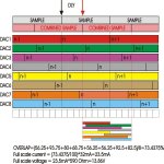
I tried to draw a graphical representation of what happens with the 8 combined DAC outputs. If I am correct, overlap in the combined sample is about 73.4375%. Note that the combined sample has a delay of approx. 43.75% when compared to the main sample. One complete sample time = 100%. Full scale current is 23.5mA, full scale voltage is 13.86V when using 590 Ohm in the I/V stages.
Each DAC is represented in a different color for clarity. Combined graphic representation is in diagram below. Current sample = n, previous sample = n-1, next sample = n+1. Scale below is 8 BCK/division.
Hope this will clear things up a bit
Hi all,
I tried to draw a graphical representation of what happens with the 8 combined DAC outputs. If I am correct, overlap in the combined sample is about 73.4375%. Note that the combined sample has a delay of approx. 43.75% when compared to the main sample. One complete sample time = 100%. Full scale current is 23.5mA, full scale voltage is 13.86V when using 590 Ohm in the I/V stages.
Each DAC is represented in a different color for clarity. Combined graphic representation is in diagram below. Current sample = n, previous sample = n-1, next sample = n+1. Scale below is 8 BCK/division.
Hope this will clear things up a bit
Attachments
Adjusting MSB
Hi Bernhard,
thanks for the information [post#377]
I have spend the last days solving oscillation and hum problems with the modified tube output stage. I ended up re-arranging ground / screening scheme, modified tube power supplies and used screened cable exclusively. Finally the tube output stage is whisper silent, only weak noise is audible at maximum volume setting, hum is inaudible.
Then I played the -60dB dithered sinewave again and turned the volume all the way up. It sounded clear, hardly any background noise.
The PCM56 is a DAC using a resistive ladder network, MSB switch causes most interference as all switches change position simultaneously. Adjusting MSB could reduce the audible effects of this MSB switchover.
The TDA1541A uses three 2-bit active dividers (decoupling capacitors are connected to this circuit), operating on the dynamic element matching principle, in combination with a 10-bit passive current divider, based on emitter scaling. All 16 currents are derived from one single reference current source. According to descriptions of this chip, glitches at MSB change, like the PCM56 are reduced due to this different setup. Externally "adjusting" MSB could cause drift, as it's no longer in "sync" with the TDA1541A internal current reference source, It takes only 61 nA current change to flip 1 LSB (4mA full scale current), see the problem. Added switching noise of 16 MSB switches plus logic (L+R channels) could make things even worse.
Listening session
Hi tubee,
Thanks for your reply [post#413]
Those cones from PMMA look very professional. I use Delrin (Acetal copolymer) for the large, medium and small sonic resonators because of the sonic properties of this material. PMMA is also very good.
I tried to invite you for a listening session, but I couldn't find your email address.
Hi Ecdesigns
Thanks very much for invitation to listen to your creation: the D-I dac (and resonators)
There are now 2 things:
1 My wife is just operated on her knees, she can walk very bad now and i "nurse" her a little, difficult to get away here now.
2 the distance to your home-residence from mine is quite far, not easy to do in one evening or so.
Anyway, email is: tubee_7 at hotmail dot com
Btw i like to work with POM too, but i had some PMMA at hand.
Re: DAC combined outputs
Drawn that way, it looks like the samples overlap but add in the timing and WS and a different picture emerges. Look as WS the signal that triggers conversion. Each negative going edge of WS is separated by 8 BCK cycles when 8 TDA's are used. 8 BCK cycles amounts to 2.84us. The converted output appears at the first positive going edge of BCK after a negative edge of WS i.e half of a BCK cycle or 0.178us include setling time and the output is stable after 0.678us. The output stage does not see another sample for more than another 2us. This is the same as a single dac connected to a 8x oversampling filter where every sample appears at an interval of (22.7/8)us.
-ecdesigns- said:Hi all,
I tried to draw a graphical representation of what happens with the 8 combined DAC outputs. If I am correct, overlap in the combined sample is about 73.4375%. Note that the combined sample has a delay of approx. 43.75% when compared to the main sample. One complete sample time = 100%. Full scale current is 23.5mA, full scale voltage is 13.86V when using 590 Ohm in the I/V stages.
Each DAC is represented in a different color for clarity. Combined graphic representation is in diagram below. Current sample = n, previous sample = n-1, next sample = n+1. Scale below is 8 BCK/division.
Hope this will clear things up a bit
Drawn that way, it looks like the samples overlap but add in the timing and WS and a different picture emerges. Look as WS the signal that triggers conversion. Each negative going edge of WS is separated by 8 BCK cycles when 8 TDA's are used. 8 BCK cycles amounts to 2.84us. The converted output appears at the first positive going edge of BCK after a negative edge of WS i.e half of a BCK cycle or 0.178us include setling time and the output is stable after 0.678us. The output stage does not see another sample for more than another 2us. This is the same as a single dac connected to a 8x oversampling filter where every sample appears at an interval of (22.7/8)us.

2 sample response
Hi rfbrw,
Thanks for your reply [post#418]
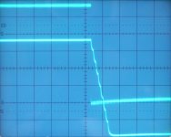
Yes you are right, there is a delay of DAC outputs 2...8, being 0.5 * BCK (177nS), typical settling time of the TDA1541A is 500nS. So a total delay of 677nS after WS negative going edge. But the same applies for DAC1 as well as it is also triggered after 0.5 * BCK. So relatively, there is only approx. 2.83uS between samples (BCK/8). Both DATA and WS are delayed by the synchronous serial shiftregister timing chain before applying them to each individual DAC2...8. At a given time all 8 DAC's have (part of) sample n at the output, as 8 individually controlled DAC's are used. This is the overlap of sample n. I used the difference between zero delay (DAC1) and max delay (DAC6) 56BCK and divided this by 2 (28BCK), being the centre point of the combined sample. Then I calculated the overlap with this point as reference.
I added a oscillogram of a squarewave transient, to illustrate this. Upper trace is the output of a a standard NOS-DAC, lower trace is the octal D-I DAC. So now we have only 2 different sample values, and can observe how the samples appear at the output. The 8 steps seen are created by sequential switch-off, of the DAC output currents. The average delay can also be seen.
Hi rfbrw,
Thanks for your reply [post#418]
Yes you are right, there is a delay of DAC outputs 2...8, being 0.5 * BCK (177nS), typical settling time of the TDA1541A is 500nS. So a total delay of 677nS after WS negative going edge. But the same applies for DAC1 as well as it is also triggered after 0.5 * BCK. So relatively, there is only approx. 2.83uS between samples (BCK/8). Both DATA and WS are delayed by the synchronous serial shiftregister timing chain before applying them to each individual DAC2...8. At a given time all 8 DAC's have (part of) sample n at the output, as 8 individually controlled DAC's are used. This is the overlap of sample n. I used the difference between zero delay (DAC1) and max delay (DAC6) 56BCK and divided this by 2 (28BCK), being the centre point of the combined sample. Then I calculated the overlap with this point as reference.
I added a oscillogram of a squarewave transient, to illustrate this. Upper trace is the output of a a standard NOS-DAC, lower trace is the octal D-I DAC. So now we have only 2 different sample values, and can observe how the samples appear at the output. The 8 steps seen are created by sequential switch-off, of the DAC output currents. The average delay can also be seen.
Attachments
- Home
- Source & Line
- Digital Line Level
- Building the ultimate NOS DAC using TDA1541A