Tubes
Hi, dddac,
Thanks for your reply [post #234],
>The differential tube output stage has become an important part of the octal D-I DAC as it seems to work perfectly with the unfiltered octal D-I DAC output signal, giving a significant improvement in sound quality. But opening a thread at the tube group is still a good idea.
>Remember there was a 352.8KHz residu signal? I use the cable capacitance in combination with the output attenuator to suppress this residu since the signal has to pass the cable anyway.
>The cathode follower is a "must" to isolate the differential triode amplifier from the output load, so it will remain in perfect balance when no differential load is used. So I didn't primarily use it to get a low output impedance.
Project progress
Hi all,
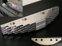
Thanks for your advice about the tube output stage. Now I will show you what I have been doing the past days, beside tube output modifications. I did some serious CNC milling, as I need to complete the basic housing first, in order to continue with the design of the main boards.
Attached photograph shows some "artwork". It's the part of the octal D-I DAC housing that reflects it's operation principle also have a look at post #220. I'ts other function is to protect / screen the tubes.
Top of the photo, CNC milling of one of the 8 tube protection plates.
Photo shows a side view of the complete tube protection assembly. Each plate represents a DAC output from the octal D-I DAC, starting with DAC1 output at the top. The DAC name is engraved in the aluminum.
Bottom of the photo, top view shows the "smooth" octal D-I DAC output reflected in the positioning of the 8 individual plates.
I did some experiments with the status indication, as mentioned in post #220. I used a lighting trick to enhance the tubes glow using 3mm high brightness LED's mounted at the centre of the tube socket. It will illuminate each tube in a spectacular way, the glow will spread among the 8 plates, you really must see this. I will make a photograph of it when the tube support plate is ready. The status indication will show you wether semiconductor or tube mode is selected, it indicates when the tube stage is warming-up, is ready for use, or is shutting down.
Hi all,
Thanks for your advice about the tube output stage. Now I will show you what I have been doing the past days, beside tube output modifications. I did some serious CNC milling, as I need to complete the basic housing first, in order to continue with the design of the main boards.
Attached photograph shows some "artwork". It's the part of the octal D-I DAC housing that reflects it's operation principle also have a look at post #220. I'ts other function is to protect / screen the tubes.
Top of the photo, CNC milling of one of the 8 tube protection plates.
Photo shows a side view of the complete tube protection assembly. Each plate represents a DAC output from the octal D-I DAC, starting with DAC1 output at the top. The DAC name is engraved in the aluminum.
Bottom of the photo, top view shows the "smooth" octal D-I DAC output reflected in the positioning of the 8 individual plates.
I did some experiments with the status indication, as mentioned in post #220. I used a lighting trick to enhance the tubes glow using 3mm high brightness LED's mounted at the centre of the tube socket. It will illuminate each tube in a spectacular way, the glow will spread among the 8 plates, you really must see this. I will make a photograph of it when the tube support plate is ready. The status indication will show you wether semiconductor or tube mode is selected, it indicates when the tube stage is warming-up, is ready for use, or is shutting down.
Attachments
Ecdesigns i have a question for you.
My CD 304mk2 had some startup problems and i managed it to repair, loose connection. But in meantimee as i work with it i want to mod this player (clock, caps, dem reclock, and more), want to keep 7220 in it and clean up the Spdif signal. Normal is a transformer between the signal, but i want to remove it.
In post 55 here you mentioned:
"As far as clocks are concerned (jitter) I make sure jitter is reduced by increasing the slew rate of the SPDIF signal right at the signal source (I use a schmitt trigger 74HC14 with a 680 OHm resistor between input and output and a 10nF capacitor between the SPDIF signal and the schmitt trigger input. Then the schmitt trigger output is fed to a differential RS422 driver chip (DS8922N) this RS422 chip is also ideal for buffering I2S signals. This way I start off with a clean SPDIF signal right at the source."
Can i build your above mentioned Schmitt trigger circuit in the 304mk2 to clean up the Spdif, or is a simple solution with a 74HC08 to a BNC output also good enough? (like this)
http://home.hccnet.nl/r.r.meijer/cdd/schema zonder trafo.jpg
Thanks for your time.
SPDIF
Hi, tubee,
Thanks for your reply,
> No I bought the PC controlled milling machines (direct graphical input) for my small electronics company I started in 1990. First I used them for milling plastic housings and printed circuit boards. Later I used these machines more often for all kind of projects. They are the best "tools" I ever bought.
> I plan to post complete schematics of the differential SPDIF interface I am using now. It uses a transformer you can make using a philips ringcore. The 74HC14 is very important for increasing the slew rate. The differential RS422 interface is ideail for transporting high frequency digital signals. For interconnection cable I use a standard high quality SVHS cable.
The third mode
Hi, all,
Time for some project updates,
Yesterday I completed the PCB design of the I/V converter & OP-amp differential amplifier. I use 2 small separate circuit boards, one for each channel. Each board has it's own power supply regulators "on board". The modules also provide direct outputs of the I/V stages to simultaneously feed the tube output stage.
The circuit diagram of the analog main board is almost ready. The following modules are placed on the analog main board:
2 X I/V stage & OP-amp differential amplifier
2 X Quad DAC module
Timing chain
This analog main board only needs a power supply and I2S input signal to function.
The differential tube output stage is ready as well. The hum is completely gone, the problem was pin 9 of the ECC82. When using a "floating" filament supply, this pin should be grounded. It also looks as if pin 9 (filament center tab) is connected to a internal screen plate. The gain, distortion and power consumption have been highly optimized. I have replaced the CF with a ECC83. I will post the schematic diagram of the new tube stage soon, this will replace the diagram I previously posted.
Yesterday late at night, while listening to the octal D-I DAC, another "thing" occured to me. The octal D-I DAC prototype setup can toggle between tube and OP-amp output (they run simultaneously). So what would happen if both, OP-amp and Tube output were connected together, and would it even work?
As already mentioned, the OP-amp diff amp has a very accurate bass (DC coupled) and an accurate almost analytical output signal, it only lacks the beautiful rich and open sound of the differential tube output. So why not give it a try and "join" both of them.
I added a swith, turned on the octal D-I DAC and allowed it to warm up. First I selected the OP-amp diff amplifier, then I added the tube output signal with the addittional switch. And yes, the warm open sound was there again...together with the accurate bass of the "analytical" OP-amp signal. I listened to it until deep in the night. Yes, this "mode" will be definitely part of the octal D-I DAC.
So we end up with 3! different output modes for the octal D-I DAC:
1) Op-amp output mode
2) Tube output mode
3) Mixed output mode (Op-amp + tube output)
Hi EC designs
very nice your design will be modular - that is a very nice and diy friendly idea! I already have boards for USB and SPDIF to I2S conversion. I asked some quotations for the TDA1541A chips, but have received no reply yet.
The idea of combining opamp and tube is new to me (well, it was new for you to until some hours ago). I like it - I have an active system, so I could even use the opamp's output for bass and the tube's output for 100Hz and up. But on the other side I know that tubes can beat opamps and SS amps when it comes to bass reproduction, so maybe there is room for improvement?!
Erik
ErikdeBest said:Hi EC designs
I asked some quotations for the TDA1541A chips, but have received no reply yet.
Erik
I've been similarly inspired by this DAC and have done some searching for TDA1541 chips myself. Can anyone confirm that it's the TDA1541 (not the A version, Sony?) that you need for I2S? I've found some for 3 pound a pop at
http://www.grandata.co.uk/acatalog/Grandata__TDA_745.html
I just called a company in England that showed the tda1541a available at a cost of 3 pounds each.
http://www.nikko-electronics.net/ca...74&PHPSESSID=0f95a75be3db011084b3f24e9f6d5edb
Actually it costs 14 pounds..each. So, for the ones (like me) that thought having found a cheap source...
Erik
http://www.nikko-electronics.net/ca...74&PHPSESSID=0f95a75be3db011084b3f24e9f6d5edb
Actually it costs 14 pounds..each. So, for the ones (like me) that thought having found a cheap source...
Erik
I bought the 1541A's here in a group buy for 6,15 Eu each. Maybe he has still some left. Bought them from Bruno.
Hi Tubee
I also bought 4 TDA's in a group buy. They were ordered from Reichelt, but they don't have them anymore.
I placed a WTB on the market place for 16 pieces, for 2 DAC's - one for myself, the other for a friend who lives at the same student house. Let's see if can get them for not to much money (they seem available from various sources, but prices are about 13 euros/piece now)
Erik
Ecdesigns:
 , one way to get some of the effect you are looking for would be trying Riken-Ohm resistors on any R on the signal analog path. This had allways helped me, in my limited experience...
")
Good luck
M
At the risk of receiving unplesant replies from technically oriented matesAs already mentioned, the OP-amp diff amp has a very accurate bass (DC coupled) and an accurate almost analytical output signal, it only lacks the beautiful rich and open sound of the differential tube output.
, one way to get some of the effect you are looking for would be trying Riken-Ohm resistors on any R on the signal analog path. This had allways helped me, in my limited experience... Good luck
M
ECdesigns:
Perhaps the best thread I've seen on DIY digital. I would love to build this kit if available. My question is, have you tried running the op amp output stage unregulated on very low-impedance SLA batteries? I suspect that if you tried this you might abandon a tube ouput stage. My reference is the Enersys Odyssey PC2150 (12V/100 AH/2.2 milliohm internal resistance), filtered at the application with parallel array of low-ESR caps such as 10 or more Rubycon ZA 470uf/16V.
Dave
MGH said:vatofale...As the title of this thread indicates,
"Building the ultimate NOS DAC using TDA1541A"
My bad, too much reading in circles
ErikdeBest said:I just called a company in England that showed the tda1541a available at a cost of 3 pounds each.
http://www.nikko-electronics.net/ca...74&PHPSESSID=0f95a75be3db011084b3f24e9f6d5edb
Actually it costs 14 pounds..each. So, for the ones (like me) that thought having found a cheap source...
Erik
Grandata do appear to have TDA1541A chips for 6 pounds each (www.grandata.co.uk catalogue search will bring them up).
The sound of resistors
Hi, maxlorenz
Thanks for the tip [post#255],
> After reading some articles on the internet about the "carbon resistor" sound, an important factor is noise. Wirewound (foil) resistors have the lowest noise, followed by metal film, metal oxide, carbon film, and carbon composition. Noise is also proportional to the current that flows trough a resistor, higher current, more noise. Also higher Ohmic values will increase noise, higher resistance, more noise. Noise can be reduced by using higher wattage types.
Carbon (composition) resistors seem to produce noise similar to "pink" noise, when a alternating current runs trough these resistors (audio signal) the "noise is modulated (increased current produces more noise) by the audio signal, but not all frequencies produce the same noise level this way. So the sound get's "colored" and determines the resistor's "sound". Technically, if you want to create a signal that is as clean as possible, NON-inductive wirewound or metal foil resistors are a good choise, followed by high wattage metal film.
But then, you might like this effect and the (carbon composite) Riken-Ohm resistors are an enrichment of the sound quality. Others might prefer a clean signal with nothing added to it. I try to keep the signal as clean as possible because a lot of "things" are already added to the sound along the audio chain.
Tubes produce a more open "warm" sound. This "sound" persists even with very low distortion levels. A tube is a very "basic" one component amplifier that needs little feedback (depends on tube gain). An OP-amp is a complex circuit composed of many individual semiconductors, resistors and capacitors. In order to produce low distortion it needs a fair amount of feedback. I think, feedback can compromise the audio signal. With feedback, you need a specific amount of time to get the output signal "locked" to the input signal. It's basically a "servo" loop. The audio signal disrupts this "servo" loop causing distortion being added to the audio signal, during the time this "servo" tries to lock-in again. This "servo" noise is one of the factors that determine the "sound" of an amplifier stage. The amplifier that responds very quickly, without overshoot or "ringing", and does the "locking" in the same way over the entire audio spectrum will have the most neutral "best" sound.
Question is, what sound comes closest to natural sound, tube sound, semiconductor sound or both mixed together. I think this question can only be answered by listening sessions and direct comparison. Fact is, the octal D-I DAC will have all 3 options, and they can be "toggled" directly during listening.
ECdesigns:
I too generally prefer zero-feedback tube designs over SS. My observation about trying op amps on batteries comes from another direction that may or may not be relevant to your goals, depending on whether you're aiming to market. First, regarding choice of preferred output tubes for a CDP/DAC, in the States at least we see that custom designers like ModWright & APL (who modify commercial players), as well as hi-end manufacturers like BAT and Audio Research, increasingly prefer the 6H30 tube. Have you considered this tube? Even at that, within the community of hard core tube audio buffs, many still prefer SS to tubes when choosing a very hi-end CDP/DAC. So, yes, it's a great idea to include both SS and tubes in your design; the question becomes how to get both tubes and SS to the highest level for a fair comparison. Personally, I've found that there is no comparison between running monolithics such as BUF634 and op amps on AC/DC discrete regulation vs. unregulated low-impedance SLA batteries. The unregulated big batteries take these devices to different level in terms of grainless transparency and resolution. Also battery supplies will improve the down-regulated circuits in the DAC, such as the TDA chip. But the batteries need to be selected for low internal resistance in the 2-3 milliohm range and NiMH will not do it and many SLA will not do it. Also, you might just find that if you took this step you would no longer sense the need to complicate design & add cost with a separate tube stage. For the committed DIYer, of course, all bets are off.
Dave
- Home
- Source & Line
- Digital Line Level
- Building the ultimate NOS DAC using TDA1541A