Is there any advantage in using 100Uf 16v Tantalums? (+ve to gnd?) caps with a 1uf dem clock cap? (also Tantalum).
Do Tants have lower leakage?
Ignore the above. they are too large & expensive so have opted for Nichicon UKL series very low leakage types from Mouser.
TDA1541A Dual Mono 17 bit Signed Magnitude DAC
Hi everyone,
I thought about the 17-bit DAC at leisure and, I think, found a solution.
As I wrote to colleague Alexandre, the solution of the problem is not in the plane of the software solutions, but in the plane of the "iron".
It is necessary to add to the output current of the upper segment 4 mA (more precisely: 4 mA + 61 nA). This is the key moment!
Due to this, in both segments, the output current of the TDA1541 will oscillate with an amplitude of +/- 2 mA, and the total current of the two segments will vary from 0 to 8 mA. Moreover, the high-order bit is used to determine which segment to submit the input data, after which it is deleted and does not enter the input 1541. Thus, we use information from all 17 bits. But information from the MSB is used on the analog side.
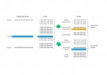
In the picture I tried to schematically depict the conversion of the input 24-bit code. First, from the 24-bit input signal, 7 low-order bits are cut out. The MSB is then analyzed and deleted. The received 16-bit signal is fed to the TDA1541 of a particular segment (upper or lower), depending on the value of the remote MSB. To the output current of the TDA1541 of the upper segment, 4 mA (current shift) is added.
At whom what thoughts?
Regards
Serg
Hi everyone,
I thought about the 17-bit DAC at leisure and, I think, found a solution.
As I wrote to colleague Alexandre, the solution of the problem is not in the plane of the software solutions, but in the plane of the "iron".
It is necessary to add to the output current of the upper segment 4 mA (more precisely: 4 mA + 61 nA). This is the key moment!
Due to this, in both segments, the output current of the TDA1541 will oscillate with an amplitude of +/- 2 mA, and the total current of the two segments will vary from 0 to 8 mA. Moreover, the high-order bit is used to determine which segment to submit the input data, after which it is deleted and does not enter the input 1541. Thus, we use information from all 17 bits. But information from the MSB is used on the analog side.
In the picture I tried to schematically depict the conversion of the input 24-bit code. First, from the 24-bit input signal, 7 low-order bits are cut out. The MSB is then analyzed and deleted. The received 16-bit signal is fed to the TDA1541 of a particular segment (upper or lower), depending on the value of the remote MSB. To the output current of the TDA1541 of the upper segment, 4 mA (current shift) is added.
At whom what thoughts?
Regards
Serg
Attachments
As I wrote to colleague Alexandre, the solution of the problem is not in the plane of the software solutions, but in the plane of the "iron".
Serg, I stand by everything I posted. It is all correct.
Before truncating the 24 bit signal you should add dither to it. To get the best possible sound you have to use a good dither algorithm. Not all dither is equal. It can make a big difference if you care to listen.
Regards,
Alex
Hi Alex,
The problem needs to be solved in hardware. It is not solved purely by software.Serg, I stand by everything I posted. It is all correct.
This is not very important. And then, dithering is more often used for ADCs.Before truncating the 24 bit signal you should add dither to it
Serg,
If you want to take full advantage of the 17-bit segmented dac you need the combination of hardware and software. I am talking about the best solution here.
Fully disagree, dither is a game changer. Back when we used digital filters the better ones had several dither options. The PMD100 is one example.
Some people feel that the type of dither has to be selected depending on the audio program material, for the best sounding result.
I gave good advice, one example of an *excellent* free dither plugin, maybe the best, and it works well with everything. It is just not ready for 17 bits, we would need to contact the programmer so he can make a small change to his source code and compile a 17-bit version.
Thanks
Alex
The problem needs to be solved in hardware. It is not solved purely by software.
If you want to take full advantage of the 17-bit segmented dac you need the combination of hardware and software. I am talking about the best solution here.
This is not very important. And then, dithering is more often used for ADCs.
Fully disagree, dither is a game changer. Back when we used digital filters the better ones had several dither options. The PMD100 is one example.
Some people feel that the type of dither has to be selected depending on the audio program material, for the best sounding result.
I gave good advice, one example of an *excellent* free dither plugin, maybe the best, and it works well with everything. It is just not ready for 17 bits, we would need to contact the programmer so he can make a small change to his source code and compile a 17-bit version.
Thanks
Alex
Hi Alex,
Respectfully,
Serg
Yes, you need to combine a software and hardware approach. But so far, a purely programmatic approach has been proposed, but it does not solve the problem.If you want to take full advantage of the 17-bit segmented dac you need the combination of hardware and software.
Dithering is used to mask quantization noise. Increasing the digit capacity much more efficiently reduces quantization noise. In today's studio recordings in the format of 24/192 or higher dithering is not usually applied.Fully disagree, dither is a game changer. Back when we used digital filters the better ones had several dither options. The PMD100 is one example.
You again offer a purely software solution. Nothing good will come of it.It is just not ready for 17 bits, we would need to contact the programmer so he can make a small change to his source code and compile a 17-bit version.
Respectfully,
Serg
Serg
No. The 17 bit segmented dac has always included glue logic, from the very first post by John. I scrutinized the logic and made posts detailing exactly what it must do.
Wrong, dithering is usually applied.
In particular, it is always applied when mastering for the CD format. Proper dither can add several bits of perceived resolution, it preserves almost all of the nuance present in the high resolution source.
The 17 bit dac is no good for high resolution material if you truncate the audio data without dithering. There is just no comparision with a properly dithered signal.
I am giving sound advice here. The bar has been raised, I have discovered this very special dither that is sounding better than any other type so far. The difference is by no means small when playing high res through a 16 bit dac. Along with SOX upsampling inside JRiver (SOX is the very best resampler, it sounds a lot better than 44.1KHz), the dither I suggested brings the result closer to high resulution analog. It brings more ambience, calmness, makes the music very natural and engaging.
When John posted the segmented dac idea I was instantly thrilled by the possibilities of the combination, this is what will take it to another level.
Sincerely
Alex
Yes, you need to combine a software and hardware approach. But so far, a purely programmatic approach has been proposed, but it does not solve the problem.
No. The 17 bit segmented dac has always included glue logic, from the very first post by John. I scrutinized the logic and made posts detailing exactly what it must do.
Dithering is used to mask quantization noise. Increasing the digit capacity much more efficiently reduces quantization noise. In today's studio recordings in the format of 24/192 or higher dithering is not usually applied.
Wrong, dithering is usually applied.
In particular, it is always applied when mastering for the CD format. Proper dither can add several bits of perceived resolution, it preserves almost all of the nuance present in the high resolution source.
The 17 bit dac is no good for high resolution material if you truncate the audio data without dithering. There is just no comparision with a properly dithered signal.
I am giving sound advice here. The bar has been raised, I have discovered this very special dither that is sounding better than any other type so far. The difference is by no means small when playing high res through a 16 bit dac. Along with SOX upsampling inside JRiver (SOX is the very best resampler, it sounds a lot better than 44.1KHz), the dither I suggested brings the result closer to high resulution analog. It brings more ambience, calmness, makes the music very natural and engaging.
When John posted the segmented dac idea I was instantly thrilled by the possibilities of the combination, this is what will take it to another level.
Sincerely
Alex
Wolfson has included some info about available dither types in this datasheet.
https://www.mouser.com/ds/2/76/WM8741_v4.3-1141934.pdf
First, please notice:
And consider that the dac is 24 bits (the Wolfson). For our proposed 17 bit dac it is even more important to dither.
Continuing:
They included an option to disable dither as well. Probably to demonstrate the need for dithering. OTOH, I suppose it might even suit some people and some (very unpleasant) music genres, as they tend to overcompress and even intentionally clip that garbage nowadays. Lack of dither will bring a harsh/ edgy / annoying / hard sound if that is what you are after, I certainly am not.
Final note: NotJustAnotherCD is better than all of these dither types and is working well with everything. Speech, movies and every musical genre. On some of my high resolution music it made an amazing difference, the difference between analytical listening (where something was wrong) to truly enjoying the good music.
Sincerely
Alex
https://www.mouser.com/ds/2/76/WM8741_v4.3-1141934.pdf
First, please notice:
Dither is applied whenever internal truncation occurs.
And consider that the dac is 24 bits (the Wolfson). For our proposed 17 bit dac it is even more important to dither.
Continuing:
It is also used when a 32 bit input word is applied to the DAC prior to truncation to the internal wordlength. Three types of dither can be
selected to allow the sound quality if the device to be optimised.
TDF has a triangular probability density function and causes zero noise modulation i.e. the quantisation noise is invariant to the changes in the signal level. This mode is recommended and is selected by default.
RPDF has a rectangular probability density function and may cause noise modulation.
HPDF has a triangular probability density function with a high pass characteristic, which has a lower noise at low frequencies at the expense of raised noise levels at higher frequencies.
Alternatively the dither can be disabled.
They included an option to disable dither as well. Probably to demonstrate the need for dithering. OTOH, I suppose it might even suit some people and some (very unpleasant) music genres, as they tend to overcompress and even intentionally clip that garbage nowadays. Lack of dither will bring a harsh/ edgy / annoying / hard sound if that is what you are after, I certainly am not.
Final note: NotJustAnotherCD is better than all of these dither types and is working well with everything. Speech, movies and every musical genre. On some of my high resolution music it made an amazing difference, the difference between analytical listening (where something was wrong) to truly enjoying the good music.
Sincerely
Alex
Last edited:
You have an idealized idea of the essence of dithering. Dithering along with the merits has disadvantages. In particular, it colors the sound. But if you like dithering so much, use it.Proper dither can add several bits of perceived resolution, it preserves almost all of the nuance present in the high resolution source.
I believe that reducing the quantization noise by increasing the bit depth is more honest and effective.
Please indicate the message number where the current shift for the upper segment is proposed.The 17 bit segmented dac has always included glue logic, from the very first post by John.
This is an old idea, long ago realized in such DACs as PCM1704 and others. John tried to mechanically transfer this idea to TDA1541, not understanding the limitations of this chip.When John posted the segmented dac idea...
Serg, here it is.
Sincerely,
Alex
Also, please take notice of the two zeros at bipolar zero. That is, one of the segments needs addition of 1 LSB, otherwise there will be a repeated code at the zero crossing. The logic has to take care of this.
The last detail is when the 17 bit input is all ones. The logic should not add one lsb to this particular code.
Sincerely,
Alex
Actually I had already noticed the need for addition of 1 LSB to one of the segments, earlier in this post:
Thanks
Alex
Around bipolar zero we will only see low weight bits switching. The speed of the switching is also an error source, and the low bits switch faster than the high weight ones because of lower intrinsic capacitance (tda1541 uses emitter scaling).
Again, the zero crossing is the critical region if we care how it will sound.
Thanks,
Alex
Code:-FS 0 0000 0000 0000 0000 (dac#1 and dac#2 get all zeros) -FS+1LSB 0 0000 0000 0000 0001 (dac#2 gets the data left shifted) -0.5FS-1 0 0111 1111 1111 1111 -0.5FS 0 1000 0000 0000 0000 BPZ-1LSB 0 1111 1111 1111 1111 (dac#2 is "filled") BPZ 1 0000 0000 0000 0000 (dac#2 gets all ones and dac#1 gets the data+1LSB) BPZ+1LSB 1 0000 0000 0000 0001 (dac#1 gets 0000 0000 0000 0010) +0.5FS 1 0111 1111 1111 1111 +0.5FS+1 1 1000 0000 0000 0000 +FS-1LSB 1 1111 1111 1111 1110 (dac#1 gets 1111 1111 1111 1111) +FS 1 1111 1111 1111 1111
Thanks
Alex
You have an idealized idea of the essence of dithering. Dithering along with the merits has disadvantages. In particular, it colors the sound. But if you like dithering so much, use it.
You´re wrong Serg, truncation is noise and sounds bad. Truncation is much worse than color, you anihilate depth, naturalness, nuance like reverb tails.
A good dither algorithm preserves the original signal and brings our digital creations closer to the highest possible quality. I am impressed with that dither plugin and giving good advice here.
This is an old idea, long ago realized in such DACs as PCM1704 and others. John tried to mechanically transfer this idea to TDA1541, not understanding the limitations of this chip.
You demean the valuable and intelligent input of John and mine as well. Please stop doing this to your colleagues.
-Alex
This is not about adding 1LSB, but about adding FS. And this addition needs to be done on the analog side, because there is no other way out.Actually I had already noticed the need for addition of 1 LSB to one of the segments
And in my thoughts was not. I'm just trying to protect him from error.Actually I had already noticed the need for addition of 1 LSB to one of the segments
This is not about adding 1LSB, but about adding FS. And this addition needs to be done on the analog side, because there is no other way out.
Serg, you are wrong, the problem can be solved entirely in the glue logic that precedes and controls two TDA1541 channels.
On the analog side you just connect the two current output pins together and proceed as usual.
I will stop repeating myself now.
-Alex
So let it be written, so let it be done.. The logic has to take care of this.
This is not about adding 1LSB, but about adding FS. And this addition needs to be done on the analog side, because there is no other way out.
It seems to me that your concern is not being able to HOLD one channel at the correct value while the other increases the count?
I assure you this is perfectly possible. These old school dacs have no internal processing of any kind, whatever code you input will be passed to the registers and DIRECTLY control each bit.
The original idea as posted by John is sound and valuable.
You're getting too excited, Alex. I will answer you tomorrow, when you cool down a little.The original idea as posted by John is sound and valuable.
Best wishes,
Serg
I´m fine Serg. A bit tired of repeating myself.
I use bold and uppercase to highlight the most important words. To make it clearer, better understood.
Do you understand now? You can hold one channel at zero, or -4mA, just by holding the code at the channel input. There is no need to do it on the analog side.
-Alex
I use bold and uppercase to highlight the most important words. To make it clearer, better understood.
Do you understand now? You can hold one channel at zero, or -4mA, just by holding the code at the channel input. There is no need to do it on the analog side.
-Alex
I do not agree, Alex. Without adding 4 mA on the analog side, the upper and lower segments will change the output current in the range 0 ... -4 mA. But it is necessary, that the current of the upper segment change within the limits of -4 ...- 8 mA. After all, the segments work in turn.Do you understand now? You can hold one channel at zero, or -4mA, just by holding the code at the channel input. There is no need to do it on the analog side.
- Home
- Source & Line
- Digital Line Level
- Building the ultimate NOS DAC using TDA1541A