Interesting article, thanks. Also worth reading "Dynamic Element Matching for High-Accuracy Monolythic D/A Converters" in the IEEE Journal of Solid-State Circuits, Vol. SC-11, No. 6, December 1976.
BTW I read several times that the different DEM filtering capacitors make different sound. One of my friends swears on Black Gate NX Hi-Q, others to Elna Silmic. It is beyond me what could cause the sonic difference. Anybody could explain it?
Could be as simple as dissipation factor and ripple current?
One of my friends swears on Black Gate NX Hi-Q, others to Elna Silmic. It is beyond me what could cause the sonic difference. Anybody could explain it?
I would guess leakage current. That becomes an error term since it alters the actual bit magnitude and hence linearity of the dac.
I wouldn't use an electrolytic cap on any of the filter pins.
I would guess leakage current. That becomes an error term since it alters the actual bit magnitude and hence linearity of the dac.
I wouldn't use an electrolytic cap on any of the filter pins.
Couldn't agree more....
Interesting article, thanks. Also worth reading "Dynamic Element Matching for High-Accuracy Monolythic D/A Converters" in the IEEE Journal of Solid-State Circuits, Vol. SC-11, No. 6, December 1976.
Yes, I read this article. Here's another article on the same subject: "A Monolithic Dual 16-Bit D/A Converter", IEEE JOURNAL OF SOLID-STATE CIRCUITS, VOL. SC-21, NO. 3, JUNE 1986
It is beyond me what could cause the sonic difference. Anybody could explain it?
Theoretically, there should be no effect, although I also met such statements. Perhaps it is a psychological effect (self-hypnosis), maybe something else.
I once noted in this forum that minimum leakage current is important for shunt capacitors (otherwise violated precision of reference current). Perhaps this is the reason the effect of these capacitors on the sound.
Hi oshifis,
Typical leakage current of electrolytic caps is in the uV range (around 3uA or 3000nA typical).
The LSB current equals 61nA. The different sound is most likely the sound of distortion")
BTW I read several times that the different DEM filtering capacitors make different sound. One of my friends swears on Black Gate NX Hi-Q, others to Elna Silmic. It is beyond me what could cause the sonic difference. Anybody could explain it?
Typical leakage current of electrolytic caps is in the uV range (around 3uA or 3000nA typical).
The LSB current equals 61nA. The different sound is most likely the sound of distortion
Just to ram that last line home:
Several of the bit-filter pins are approx. 6v away from 0v.
You might re-consider this as suggesting the required PCB surface leakage plus the leakage of any filter cap on the pin should not exceed ~100Mega-ohms to not affect the bit value by +/- 0.5LSB.
This requires a scrupulously-clean PCB for a start.
(Of course the lower 10bit divider is internal to the dac, so it is not quite this critical, but the point remains - think about what you are trying to achieve overall)
Last edited:
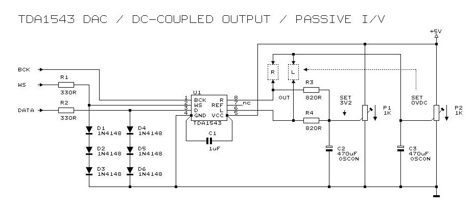
im sorry for being obnoxious but i keep needing to bring up this tda1543 circuit.
i've tried it twice now, one on a 6v battery power, and the other on an8006, both with dddac's resistor values (910ohm), p1 set at 3.8v (it does seem to get cleaner all the way up to 4.7v tho) p2 set at 2.3v (2.2 sounds neutral while dddac's recommended 2.5v sounds warmish thick)
the whole circuit certainly sounds impressive with better dynamics and clarity than the regular passive version but with the dc coupling, harmonics are definitely thin that it feels no different from listening to a delta sigma dac. sure enough, disabling the dc circuit brings back the rich harmonics yet takes away that explosive dynamic.
i'd like to know what is the main cause for the increase in dynamic. my beginner's intuition says that it's because the circuit is somewhat of a semi active, and that the series resistor is what sucks away the harmonics. i'd like to know if the same benefit in dynamics can be achieved with a separate 2.2v circuit feeding the ground.
i've also tried doubling the value of c2 to see if it affects the lost dynamic but the result is negative.
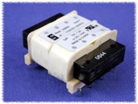
To feed my 1541/XMOS build, I am choosing a transformer.
I have been working on a power supply, selecting transformers. Some versions have split bobbins, stacked side to side with each other; and on testing this gave a very low capacitance between primary and secondary: the small one being 10 pF and the bigger one from Ropla as low as 16 pF.


This I compared with a 'standard' square transformer (bobbins consisting of layers on top of each other) and toroid transformer, having typical 200/250 pF and 400 pF capacitance between P/S.
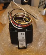
Lo and behold: also this was a very low capacitance type, like 25 pF, even though the layers were placed on top of each other like a normal square transformer.
The trade secret is told by the following pictures: There is a big air gap betweem the primary and secondary, and no, that is not for efficient cooling.


It is a clear choice for me:
albert
I have been working on a power supply, selecting transformers. Some versions have split bobbins, stacked side to side with each other; and on testing this gave a very low capacitance between primary and secondary: the small one being 10 pF and the bigger one from Ropla as low as 16 pF.
This I compared with a 'standard' square transformer (bobbins consisting of layers on top of each other) and toroid transformer, having typical 200/250 pF and 400 pF capacitance between P/S.
- Not what you would like in your power supply, to feed a jitter sensitive device . . as John has advocated here before.
Lo and behold: also this was a very low capacitance type, like 25 pF, even though the layers were placed on top of each other like a normal square transformer.
The trade secret is told by the following pictures: There is a big air gap betweem the primary and secondary, and no, that is not for efficient cooling.
It is a clear choice for me:
- I must use the versions with a low coupling.
- And reduce the number of transformers as capacitance of transformers connected parallel is additive.
- I need the same quality all along the audio path - because using a toroid in a line stage with 400 pF coupling I will destroy all the effort made before it in the chain in selecting a low capacitance .
albert
Hi dear Triode_al,
Good one.
Maybe that is one of the reasons why R core (or C core) Tx sound so good.
I rejoice when I dismantle a machine with split bobines even if later I don't use them, hehe.
Maybe we have to wind our own Tx's.
I wonder if you have tried John's charge-transfer supply (I don't remember).
Cheers,
M.
To feed my 1541/XMOS build, I am choosing a transformer.
I have been working on a power supply, selecting transformers. Some versions have split bobbins, stacked side to side with each other; and on testing this gave a very low capacitance between primary and secondary: the small one being 10 pF and the bigger one from Ropla as low as 16 pF.
Good one.
Maybe that is one of the reasons why R core (or C core) Tx sound so good.
I rejoice when I dismantle a machine with split bobines
even if later I don't use them, hehe.Maybe we have to wind our own Tx's.
I wonder if you have tried John's charge-transfer supply (I don't remember).
Cheers,
M.
other solution for power
i agree with ,that it is good to have powersupply with as low as possible capacitance to anything.
that why i use dc/dc coverters in my dacs.
in medical equipment they use them for years .
advantages:a-low cost b-low capacitance c- galvanic isolation d-easy to provide more then one voltage e-it makes small PCBs possible.
futhermore i feed the dc/dc converters with another 12Vsmps with power cord.
so no 220v on print ,safety.
see my site.
greet marius
Hi dear Triode_al,
Good one.
Maybe that is one of the reasons why R core (or C core) Tx sound so good.
I rejoice when I dismantle a machine with split bobines
Maybe we have to wind our own Tx's.
I wonder if you have tried John's charge-transfer supply (I don't remember).
Cheers,
M.
I am at the same stage of planning. What do you think of the Hammond 229 series. Seems to have many of the features we seek.
Attachments
Custom Transformers for TDA1541A and other parts
Hi all,
I'm cleaning up my project parts from the past few years on the TDA1541A since my project is finished and my "dream machine" is running nicely.
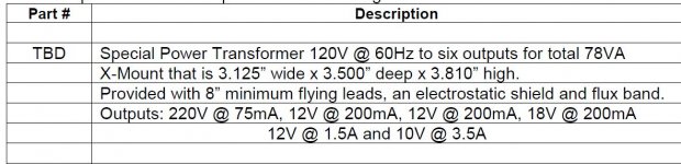
I was not happy with the transformers I could find, and wasn't thrilled with using several in a chassis, so I had Hammond custom wind some for me. I had 4 made to meet the minimum NRE charge. Here's the specs:
* Flux band for very low/ no leakage
* 6 windings total
220V RMS, 75mA
12V, 1.5A
12V, 200mA
12V, 200mA
18V, 200mA
10V, 3.5A
I have only 2 for sale.
Also, over the last 12 years, since becoming interested in the TDA1541A, I have accumulated quite a few TDA1541A chips, of which I'm also selling. The collection includes *one* Double Crown and some R1 devices.
If anyone's interested, please PM me for a list, prices and other project items related to the TDA1541A only.
Thanks to everyone in this thread over the years for making this a great and rewarding project to work on!
Gary
Hi all,
I'm cleaning up my project parts from the past few years on the TDA1541A since my project is finished and my "dream machine" is running nicely.
I was not happy with the transformers I could find, and wasn't thrilled with using several in a chassis, so I had Hammond custom wind some for me. I had 4 made to meet the minimum NRE charge. Here's the specs:
* Flux band for very low/ no leakage
* 6 windings total
220V RMS, 75mA
12V, 1.5A
12V, 200mA
12V, 200mA
18V, 200mA
10V, 3.5A
I have only 2 for sale.
Also, over the last 12 years, since becoming interested in the TDA1541A, I have accumulated quite a few TDA1541A chips, of which I'm also selling. The collection includes *one* Double Crown and some R1 devices.
If anyone's interested, please PM me for a list, prices and other project items related to the TDA1541A only.
Thanks to everyone in this thread over the years for making this a great and rewarding project to work on!
Gary
Hi dear Triode_al,
Maybe we have to wind our own Tx's.
I wonder if you have tried John's charge-transfer supply (I don't remember).
Cheers,
M.
Yes winding up our own
No, I didn't test the CT-supply. I would think that it does not reduce capacitative coupling; just it provides an earth where the initial capacitor load current is more absent.
- From playing around with tubes I found out that sometimes just having a DC power supply for the heaters the spikes (and even signal) would show up elsewhere even if there was no direct DC link via earth. I guess this might also be capacitance . . .
- I tested a output transformer that was straight to 90 kHz then has a dip to -20 db but passed everything above 2 MHz. . So instead of having a capacity meter we should also test with a wide-band sine generator.
Yes winding up our own
No, I didn't test the CT-supply. I would think that it does not reduce capacitative coupling...
[/LIST]
albert
Probably not and even add the Mosfet gate capacitance, yet sonically it is far superior than conventional aproach.
- From playing around with tubes I found out that sometimes just having a DC power supply for the heaters the spikes (and even signal) would show up elsewhere even if there was no direct DC link via earth. I guess this might also be capacitance . . .
- I tested a output transformer that was straight to 90 kHz then has a dip to -20 db but passed everything above 2 MHz. . So instead of having a capacity meter we should also test with a wide-band sine generator.
The road to good sound is the figth against noise I add empirically wide band inductors to all ground interconnections between active boards or to nodes, at present...
Cheers,
M.
PS: nice transformers guys.
Hi vandenberg,
Keep in mind that SMPS are EMI generators that pollute everything attached or near to it. The unshielded mains wiring distributes SMPS interference all over the building.
The power supply is in the signal path (just draw an ac diagram), so you basically placed an EMI generator right in series with the signal. I personally wouldn't do that.
i agree with ,that it is good to have powersupply with as low as possible capacitance to anything.
that why i use dc/dc coverters in my dacs.
Keep in mind that SMPS are EMI generators that pollute everything attached or near to it. The unshielded mains wiring distributes SMPS interference all over the building.
The power supply is in the signal path (just draw an ac diagram), so you basically placed an EMI generator right in series with the signal. I personally wouldn't do that.
Hi,-ecdesigns-
If you are using a local shunt regulator, the signal current is closed through it.
The power supply is in the signal path (just draw an ac diagram), so you basically placed an EMI generator right in series with the signal.
If you are using a local shunt regulator, the signal current is closed through it.
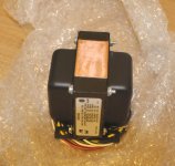
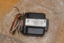
Hammond Custom Transformer for TDA1541A DAC
For those who have inquired, here's what a custom transformer looks like. Single solution is ultimately better that multiple transformers in a cabinet. Note the copper flux band running the circumference of the transformer. The transformer runs cool and very quiet, DAC performance is outstanding with no sign at all of 60Hz (or harmonics) noise injected in.
Size is as shown.
Regards,
Gary
Attachments
I was thinking, aren´t diode rectifiers just as bad as SMPS, with their switching? They certainly are generating EMI on both the mains and the subsequent circuit.
SMPS can operate at a chosen optimal frequency that can be very well filtered.
Active PFC (power factor correction) can make the mains current close to senoidal.
So, I think a well designed smps can be better than diode rectifiers.
Of course, the audio currents needs to be decoupled and separated from the pulse currents of the supply. Shunt regulators come to mind.
Just some thinking.
-Alex
Keep in mind that SMPS are EMI generators that pollute everything attached or near to it. The unshielded mains wiring distributes SMPS interference all over the building.
The power supply is in the signal path (just draw an ac diagram), so you basically placed an EMI generator right in series with the signal. I personally wouldn't do that.
I attached latest TDA1541A circuit schematics:
- DEM synchronizer circuit
- I2S attenuators
- I/V converter
I/V converter uses a plain (unselected) 2SK170-BL JFET and a 10K bias resistor. Actual I/V conversion is fully passive as the JFET merely passes the DAC output current as is. Gate current is much lower than LSB current.
I use +5V as reference instead of GND. This excludes +5V power supply from the direct signal path as I measure directly across the I/V resistor.
This converter provides simplest and cleanest output signal as the actual I/V converter consists of a single 500R resistor. All other options require active amplification and / or transformers that will introduce additional distortion.
Output coupling cap needs to be added to block DC. The hybrid coupling cap that performs closest to DC coupling was composed by paralleling 2.2uF/250V Monacor MKT, 3.3uF/250V Monacor MKT and a 40pF Teflon trimmer (set to max. value).
Hi,
Thank you for very interesting work!
I have implemented your nice IV-converter and it works fine on the test bench. But now I want to hear it in my system and got some questions:
The output must be taken over the 500R resistors and with +5v as reference, but when connecting to my amp this will be connected to amp ground...problem?
Normally a capacitor output has a bleeder resistor to gnd on the output side to discharge cap, should this be connected to gnd or +5v?
Can the 500R be changed to 680 or 1000R if I need more output and what are the limits, drawbacks?
Hi Skorpio,
The I/V stage built around the 2SK170 is outdated, one of the problems is that it exceeds TDA1541A output compliance.
The adjustable DC reference voltage takes care of this. It consists of a 1K trimmer with a 1000uF cap between wiper and GND, and another 1000uF cap between the wiper and +5V.
The voltage at the wiper serves as GND connection for the RCA sockets. This works as long as this reference voltage is not short-circuited by other connected equipment.
The trimmer is set for lowest possible DC voltage reading between the wiper of the trimmer and both RCA outputs.
This design requires no coupling caps, it ensures highly transparent playback with optimal bass response and ease of mind that one exceeds the performance of the best film caps available.
Not with the 5V supply. When the supply voltage (for the I/V stage only!) is increased, to say to 10V, it is possible to double the output amplitude by using a 1K I/V resistor. Disadvantage is that the selected bit currents no longer flow back into the 5V supply like the unselected bit currents do. This leads to higher ripple voltage on the 5V supply and increased on-chip jitter levels.
The I/V stage built around the 2SK170 is outdated, one of the problems is that it exceeds TDA1541A output compliance.
The output must be taken over the 500R resistors and with +5v as reference, but when connecting to my amp this will be connected to amp ground...problem?
The adjustable DC reference voltage takes care of this. It consists of a 1K trimmer with a 1000uF cap between wiper and GND, and another 1000uF cap between the wiper and +5V.
The voltage at the wiper serves as GND connection for the RCA sockets. This works as long as this reference voltage is not short-circuited by other connected equipment.
The trimmer is set for lowest possible DC voltage reading between the wiper of the trimmer and both RCA outputs.
Normally a capacitor output has a bleeder resistor to gnd on the output side to discharge cap, should this be connected to gnd or +5v?
This design requires no coupling caps, it ensures highly transparent playback with optimal bass response and ease of mind that one exceeds the performance of the best film caps available.
Can the 500R be changed to 680 or 1000R if I need more output and what are the limits, drawbacks?
Not with the 5V supply. When the supply voltage (for the I/V stage only!) is increased, to say to 10V, it is possible to double the output amplitude by using a 1K I/V resistor. Disadvantage is that the selected bit currents no longer flow back into the 5V supply like the unselected bit currents do. This leads to higher ripple voltage on the 5V supply and increased on-chip jitter levels.
- Home
- Source & Line
- Digital Line Level
- Building the ultimate NOS DAC using TDA1541A