Single chip PCM56 should be ugly.
It is done in really old, cheap CDPs, the idea is of "cost reduction" when you could use 1 mono chip instead of 2 chips. Twice cheapr!
The performance is bad, that's why you don't see 'em in DIY.
Really weird thing, the separation of left and right channel samples is being done in ANALOG domain, with analog switches driven by LRCLK signal. Sample/Hold may be there too, somewhere.

Hi ST3P,
Thanks
This Akai CD players with one PCM56 and two Toshiba op was the best tweaked one I had. Better than tweaked TDA1541, 1540, 1543, 1545, PCM1701, AD1865, SA78xx. but I never heard top DAC or top cd players. I think pcm56 is not a low quality dac chip. Texture of Saxophone, harmonica were the better I heard at home. Hmmm maybe I woud wait for a second pcm56... but I'm sure that the difference is not really here. Nagra make cd players with "normal" dac chip with good result. I would buy 2 ad1862 but too expensive for my little technical skill. So i have some TDA to play with... but the I/V & buffers stages... but the input stage with I2S longer than 3 inches...Hargh with which clock: WHO have I to believe. Why not try too Bernard pcm56 & analog filter way ? (but not with 32 chips...too dangerous all this boards with champagnes... plop....bubbles...burn...s....t my DAC !). I would like a good dac for my squeeze box and i'm not really sure that a bad tweaked I2S from a squeezebox is better than a good Spidf chip receiver...
Last edited:
hi studiostevus,
I see this is a quite old post, but i hope you can still answer my question.
Can you tell me which capacitor you settled on? I'm curious about your comments regarding the acrylic SMD caps. I also use 1uF/16V (low impedance Panasonic) and find them not so transparent, and a bit heavy in bass. I have read that it's not so much the type, but the larger value that has this effect.
My caps are mounted directly beside the socket pin, so electrically they are as close as possible to the pin to mitigate any impedance issues.
I'm going to try a 0.22uF and see how they sound. I'd be interested in hearing from anyone else who has found any differences in this regard.
Thanks!
Gary
Thanks John, very interesting!
I am currently running on Salas shunts, and playing around with the local decoupling of the power supply lines. What are your findings there? I see you only use a 1uF acrylic at the tda.
I have tried combinations of
-1uF acrylic smd
-22 uF BG STD
-270 uF Oscon SEPC
Not sure what I like best...
-22uF BG only --> seems like things are missing
-22uF BG + 1uF SMD --> added smoothness
-22uF BG + 1uF SMD + 270 uF Oscon --> Added bass
-1uF acrylic SMD only --> listening to it now, it seems very bass-heavy, but also liquidy smooth. I am not sure if I like the amount of bass... on the other hand it's quite analog now. It's less transparent though
What do you think?
Actually I got oscillations using salas regulators and decoupling caps.... So needed to remove all of them. Will try if there are any combinations that don't oscillate in the future....
Roger
I was pretty happy with OSCON SEPC 270u bypassed with a small film cap. .47n I think. Then ADDED BG N caps soldered directly on the tda pins. The BG definitely added as always that nice dark background and rich detail. Can't remember exact value of BG but likely 47uf. I think the key is to put the BG right on the pin IMHO. Sounds so darn good I just don't go back to mess with it.
Walter
Hi all,
I was referring to the DEM caps - 7 per side on the TDA1541A that Philips specified as 0.1uF in the data sheet. With such large values, I think you are talking about power supply decoupling capacitors?
I was referring to the DEM caps - 7 per side on the TDA1541A that Philips specified as 0.1uF in the data sheet. With such large values, I think you are talking about power supply decoupling capacitors?
Roger
I was pretty happy with OSCON SEPC 270u bypassed with a small film cap. .47n I think. Then ADDED BG N caps soldered directly on the tda pins. The BG definitely added as always that nice dark background and rich detail. Can't remember exact value of BG but likely 47uf. I think the key is to put the BG right on the pin IMHO. Sounds so darn good I just don't go back to mess with it.
Walter
Hi all,
I was referring to the DEM caps - 7 per side on the TDA1541A that Philips specified as 0.1uF in the data sheet. With such large values, I think you are talking about power supply decoupling capacitors?
My mistake. I thought you were referring to the power supply.
Hi oshifis,
Interesting...
What DEM circuit (pins 16, 17) have you implemented?
Interesting...
What DEM circuit (pins 16, 17) have you implemented?
As for the 2x7 DEM filtering capacitors, I have been listening to the DAC with the capacitors removed altogether for a while. Same as with NOS, it shouldn't work, but it sounds impressive!
but it sounds impressive!
Hi, oshifis; what is it impressive?
I connected an 510 pF silver-mica capacitor between pin 16-17. This resulted in 176.4 kHz DEM oscillator frequency. I was hoping that the frequency will lock to 4x fWS, but for some reason it does not.
Apart from this, after removing the DEM filter capacitors, the sound is very realistic, life-like. It is worth trying, especially because it costs nothing.
Apart from this, after removing the DEM filter capacitors, the sound is very realistic, life-like. It is worth trying, especially because it costs nothing.
I was hoping that the frequency will lock to 4x fWS, but for some reason it does not.
It needs a trimmer.
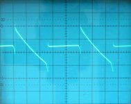
I tried tuning with an air trimmer, but it did not work either. I have an accurate frequency counter, and it was possible to tune the frequency to exactly 176.400 kHz. Then I checked the lock condition by triggering the oscilloscope externally with the WS signal, and checking the steps of the DEM switching on one decoupling pin (measuring the DEM frequency on the capacitor would de-tune the oscillator due to capacitive load). Ideally I should have seen clean synced 4-steps signal. I have seen a jittery smeared signal, instead. Also it is easy to de-tune the DEM oscillator by closing my hand to the capacitor.
Have you tried ecDesigns solution of a 1000pf (1nF) capacitor to get an (approximate) 80KHz DEM clock? According to John, this results in adequate emitter tail currents being generated if 1uF decoupling caps are used. It seems that after reading the last 100 or so posts, "locking" isn't critical, at least according to ecdesigns. (or, please correct me if am wrong, John)
Right now, I have his original solution; using a 1.8nF capacitor. Since I implemented this last September, he has changed his mind on this value (he does do that after doing more research) and says the 1nF will be better.
I do find the sound right now to be a bit dark, but I've heard several theories on this, one being the 1uF are a bit large value for the decoupling - perhaps OK for the first 2 or 3 positions, but stick with 0.1uF/0.22uF for the others. I'm using the CD 1210 Acrylics. Can't find much info regarding a qualitative sound difference of this composition vs polypropylene, so perhaps that's a factor.
I first will try only changing the 1.8nF -> 1nF and see how that works out. If not, I may swap the higher decoupling caps -the top 3 - for 0.22uF.
I connected an 510 pF silver-mica capacitor between pin 16-17. This resulted in 176.4 kHz DEM oscillator frequency. I was hoping that the frequency will lock to 4x fWS, but for some reason it does not.
Apart from this, after removing the DEM filter capacitors, the sound is very realistic, life-like. It is worth trying, especially because it costs nothing.
Hi oshifis,
There can be a big difference between impressive and transparent sound. Impressive sound usually causes listening fatigue over time. Specific distortion can also sound impressive, one always has to be very careful not to mix-up impressive sounding distortion with transparent sound.
The DEM decoupling caps have a function, removing them can cause inconsistent performance (noise, low level distortion).
DEM decoupling is highly critical as GND noise and DC leakage currents can degrade performance.
Here is a possible solution, daisy-chain DEM decoupling (haven't tested this yet):
1uF cap between pins 7 & 8
1uF cap between pins 8 & 9
1uF cap between pins 9 & 10
1uF cap between pins 10 & 11
1uF cap between pins 11 & 12
1uF cap between pins 12 & 13
1uF cap between pin 13 & AGND (pin 5).
1uF cap between pins 24 & 23
1uF cap between pins 23 & 22
1uF cap between pins 22 & 21
1uF cap between pins 21 & 20
1uF cap between pins 20 & 19
1uF cap between pins 19 & 18
1uF cap between pin 18 & AGND (pin 5).
Decoupling values:
Bit 10, 143nF
Bit 11, 167nF
Bit 12, 200nF
Bit 13, 250nF
Bit 14, 333nF
Bit 15, 500nF
Bit 16, 1uF
Lowest bit decoupling still meets nominal value of 100nF. Injection of ground noise is greatly reduced, DC leakage current is greatly reduced.
It is also good practice to attenuate (switching) noise and mirror images (44K1, 88K2, 132K3, 176K4, 220K5 and so on) present at the DAC chip output.
I am currently experimenting with a 21 KHz Cauer-Pi low-pass filter with integrated 44K1 trap (parallel resonance circuit). Higher mirror frequencies will be handled by the low-pass function.
This filter is placed between DAC chip output and I/V stage input. The filter is loaded with approx. 13 Ohms (I/V stage input impedance). The Cauer filter is dimensioned such way that a trebles-boost is obtained by shaping the filter response.
This method can also be used with passive I/V conversion (I/V resistor on the DAC chip output), but the filter values have to be recalculated for the different load impedance (I/V resistor value).
here is an online calculator for Cauer Pi filters:
Chebyshev Pi LC Low Pass Filter Calculator
For 27 OHms I/V resistor (load impedance) for example one gets following values for 3 filter components: 289nF, 235uH, and 289nF.
It is important to use air core chokes.
The shunt capacitor value (44K1 trap) can be calculated with this LC series resonance calculator:
LC Resonance Frequency Calculator - Ekswai
The shunt capacitor for the 235uH choke would be 55.4nF.
The trap works as follows, at the tuning frequency of 44K1 the impedance of the parallel resonant circuit (235uH & 55.4nF) will rise significantly. This together with the relatively low load impedance (27 Ohms in the example) will result in extra attenuation of 44K1 (sample frequency).
One can verify filter operation by using a 1 KHz test signal, it should look perfectly smooth without any visible steps on the oscilloscope.
One could experiment with I/V resistor value so the filter can be built using (combinations of) standard E12 values for caps and choke.
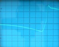
When the DEM oscillator timing cap has the correct value there should be a lock, however, due to drift (temperature) lock-out can occur over time. The jitter is quite normal with the datasheet app, performance can be optimised by using an un-interrupted ground plane and very small (805 size) film cap with shortest possible traces.
EMI pick-up can be greatly reduced by the following:
6K8 between pins 15 & 16
6K8 between pins 15 & 17
Timing cap between pins 16 & 17 (value has to be increased due to reduced oscillator input impedance).
Attached picture of the DEM clock shows the typical DEM oscillator signal for this free running DEM clock.
As for the 2x7 DEM filtering capacitors, I have been listening to the DAC with the capacitors removed altogether for a while. Same as with NOS, it shouldn't work, but it sounds impressive!
There can be a big difference between impressive and transparent sound. Impressive sound usually causes listening fatigue over time. Specific distortion can also sound impressive, one always has to be very careful not to mix-up impressive sounding distortion with transparent sound.
The DEM decoupling caps have a function, removing them can cause inconsistent performance (noise, low level distortion).
DEM decoupling is highly critical as GND noise and DC leakage currents can degrade performance.
Here is a possible solution, daisy-chain DEM decoupling (haven't tested this yet):
1uF cap between pins 7 & 8
1uF cap between pins 8 & 9
1uF cap between pins 9 & 10
1uF cap between pins 10 & 11
1uF cap between pins 11 & 12
1uF cap between pins 12 & 13
1uF cap between pin 13 & AGND (pin 5).
1uF cap between pins 24 & 23
1uF cap between pins 23 & 22
1uF cap between pins 22 & 21
1uF cap between pins 21 & 20
1uF cap between pins 20 & 19
1uF cap between pins 19 & 18
1uF cap between pin 18 & AGND (pin 5).
Decoupling values:
Bit 10, 143nF
Bit 11, 167nF
Bit 12, 200nF
Bit 13, 250nF
Bit 14, 333nF
Bit 15, 500nF
Bit 16, 1uF
Lowest bit decoupling still meets nominal value of 100nF. Injection of ground noise is greatly reduced, DC leakage current is greatly reduced.
It is also good practice to attenuate (switching) noise and mirror images (44K1, 88K2, 132K3, 176K4, 220K5 and so on) present at the DAC chip output.
I am currently experimenting with a 21 KHz Cauer-Pi low-pass filter with integrated 44K1 trap (parallel resonance circuit). Higher mirror frequencies will be handled by the low-pass function.
This filter is placed between DAC chip output and I/V stage input. The filter is loaded with approx. 13 Ohms (I/V stage input impedance). The Cauer filter is dimensioned such way that a trebles-boost is obtained by shaping the filter response.
This method can also be used with passive I/V conversion (I/V resistor on the DAC chip output), but the filter values have to be recalculated for the different load impedance (I/V resistor value).
here is an online calculator for Cauer Pi filters:
Chebyshev Pi LC Low Pass Filter Calculator
For 27 OHms I/V resistor (load impedance) for example one gets following values for 3 filter components: 289nF, 235uH, and 289nF.
It is important to use air core chokes.
The shunt capacitor value (44K1 trap) can be calculated with this LC series resonance calculator:
LC Resonance Frequency Calculator - Ekswai
The shunt capacitor for the 235uH choke would be 55.4nF.
The trap works as follows, at the tuning frequency of 44K1 the impedance of the parallel resonant circuit (235uH & 55.4nF) will rise significantly. This together with the relatively low load impedance (27 Ohms in the example) will result in extra attenuation of 44K1 (sample frequency).
One can verify filter operation by using a 1 KHz test signal, it should look perfectly smooth without any visible steps on the oscilloscope.
One could experiment with I/V resistor value so the filter can be built using (combinations of) standard E12 values for caps and choke.
Ideally I should have seen clean synced 4-steps signal. I have seen a jittery smeared signal, instead.
When the DEM oscillator timing cap has the correct value there should be a lock, however, due to drift (temperature) lock-out can occur over time. The jitter is quite normal with the datasheet app, performance can be optimised by using an un-interrupted ground plane and very small (805 size) film cap with shortest possible traces.
Also it is easy to de-tune the DEM oscillator by closing my hand to the capacitor.
EMI pick-up can be greatly reduced by the following:
6K8 between pins 15 & 16
6K8 between pins 15 & 17
Timing cap between pins 16 & 17 (value has to be increased due to reduced oscillator input impedance).
Attached picture of the DEM clock shows the typical DEM oscillator signal for this free running DEM clock.
Attachments
- Home
- Source & Line
- Digital Line Level
- Building the ultimate NOS DAC using TDA1541A