Does it mean that the whole generation chain of I2S signals has to be CML / ECL?
I plan to do a balanced 2X TDA1543 NOS, needing to invert the data line of one of the TDA1543
any CML / ECL inverter buffer to do this?
I2S signals will come from a squeezebox or async USB receiver
I plan to do a balanced 2X TDA1543 NOS, needing to invert the data line of one of the TDA1543
any CML / ECL inverter buffer to do this?
I2S signals will come from a squeezebox or async USB receiver
Something like this?
https://picasaweb.google.com/lh/photo/DJSCAhG6-Amyuf81pn4DDtMTjNZETYmyPJy0liipFm0?feat=directlink
Though I don't know if the chips are CML/ECL or whatever...
I only follow instructions.
M.
https://picasaweb.google.com/lh/photo/DJSCAhG6-Amyuf81pn4DDtMTjNZETYmyPJy0liipFm0?feat=directlink
Though I don't know if the chips are CML/ECL or whatever...
I only follow instructions.
M.
Last edited:
I am still pondering the ideal BCK supply to the tda...
The ideal BCK trigger needs to be:
- jitter-'less', so as few components between the source and the tda.
- as low voltages as possible to avoid on-chip interaction.
- but minimum 1.8V to trigger
- difference between 'low' and 'high' must be at least 800mVpp.
So the ideal BCK signal would be between 1V and 1.8V.
My divide by 4 circuit consists of 2 74AUCG1 flipflops. I have a variable supply voltage to it, so I can fine tune the output of it. At this moment I have connected the flipflop directly to pin2 of the TDA.
The result of this is that the BCK signal is low at gnd, and high at 1.8V (I have test to go below 1.8V, and then it doesnt trigger the tda anymore, in line with john's findings.
So the likely thing to do would be to pull up the 'low' to 1V (or a bit less, like 0.9V) and leave the 'high' at 1.8V. Risk of course is injection of some additional supply noise into the signal, thereby increasing jitter....
ECdesigns: http://www.diyaudio.com/forums/digi...e-nos-dac-using-tda1541a-470.html#post3329733
In the latest projects I use a high speed / low jitter divide-by-4 circuit running on 1.8V (1.8Vpp output signal). I feed this 1.8Vpp BCK signal to the TDA154x using only a 180R series resistor.
ECdesigns: http://www.diyaudio.com/forums/digi...e-nos-dac-using-tda1541a-477.html#post3411085
BCK is extremely critical, attenuators are best avoided here, even plain series resistors are a problem (noise). Best results can be achieved by using 800mVpp BCK signal (not derived from an attenuator) with less than approx. 300 Femto seconds of jitter, but this is kind of "problematic"
So simply remove the BCK attenuator and hope for the best.
The ideal BCK trigger needs to be:
- jitter-'less', so as few components between the source and the tda.
- as low voltages as possible to avoid on-chip interaction.
- but minimum 1.8V to trigger
- difference between 'low' and 'high' must be at least 800mVpp.
So the ideal BCK signal would be between 1V and 1.8V.
My divide by 4 circuit consists of 2 74AUCG1 flipflops. I have a variable supply voltage to it, so I can fine tune the output of it. At this moment I have connected the flipflop directly to pin2 of the TDA.
The result of this is that the BCK signal is low at gnd, and high at 1.8V (I have test to go below 1.8V, and then it doesnt trigger the tda anymore, in line with john's findings.
So the likely thing to do would be to pull up the 'low' to 1V (or a bit less, like 0.9V) and leave the 'high' at 1.8V. Risk of course is injection of some additional supply noise into the signal, thereby increasing jitter....
Hi studiostevus,
Ideal BCK divider (divide-by-4) can be built using ECL (> 4 GHz). Signal swing would be 800 mVpp and typical jitter contribution would be 200 Femto Seconds.
When the bias voltage is corrected to 1.2V, the clock signal would then swing between +0.8V and +1.6V.
When using 74AU1G74 D flip-flops (typical 2.5ps jitter contribution for each D flip-flop) one could do following:
2.2V power supply (buffered 2.7V zener for example).
Anti-parallel 1N4148 diodes between Q output and BCK:
Q >| BCK
Q |< BCK
100R resistor between /Q output and BCK.
This would result in BCK signal swing between +0.6V (Q = "0" and /Q = "1") and + 1.6V (Q= "1" and /Q = "0").
I am still pondering the ideal BCK supply to the tda…
Ideal BCK divider (divide-by-4) can be built using ECL (> 4 GHz). Signal swing would be 800 mVpp and typical jitter contribution would be 200 Femto Seconds.
When the bias voltage is corrected to 1.2V, the clock signal would then swing between +0.8V and +1.6V.
When using 74AU1G74 D flip-flops (typical 2.5ps jitter contribution for each D flip-flop) one could do following:
2.2V power supply (buffered 2.7V zener for example).
Anti-parallel 1N4148 diodes between Q output and BCK:
Q >| BCK
Q |< BCK
100R resistor between /Q output and BCK.
This would result in BCK signal swing between +0.6V (Q = "0" and /Q = "1") and + 1.6V (Q= "1" and /Q = "0").
Hi studiostevus,
Ideal BCK divider (divide-by-4) can be built using ECL (> 4 GHz). Signal swing would be 800 mVpp and typical jitter contribution would be 200 Femto Seconds.
When the bias voltage is corrected to 1.2V, the clock signal would then swing between +0.8V and +1.6V.
When using 74AU1G74 D flip-flops (typical 2.5ps jitter contribution for each D flip-flop) one could do following:
2.2V power supply (buffered 2.7V zener for example).
Anti-parallel 1N4148 diodes between Q output and BCK:
Q >| BCK
Q |< BCK
100R resistor between /Q output and BCK.
This would result in BCK signal swing between +0.6V (Q = "0" and /Q = "1") and + 1.6V (Q= "1" and /Q = "0").
Hi John, thanks for your note.
The 74au d flip flop solution is essentially the one you used a year ago in mk7 or so.
I am wondering whether using 2 diodes (jitter contribution) and a resistor (noise) to improve the ttl levels to reduce on-chip crosstalk, is a better solution than just leaving the ttl as is (Vlo=0v, Vhi=1.8v), having less jitter on the incoming bck signal and accepting the on-chip crosstalk....
Have you done any research on this perhaps?
In the meantime I tried the following:
74auc1g flipflop Q to pin2, and the power supply (1.8V) to the flipflop with series resistor 68R to pin2 as well. This lifts up the 'low' state to about 0.7V. So far seems stable and works fine.
Haven't yet properly compared to the situation without the pull-up resistor. Will do that tomorrow.
74auc1g flipflop Q to pin2, and the power supply (1.8V) to the flipflop with series resistor 68R to pin2 as well. This lifts up the 'low' state to about 0.7V. So far seems stable and works fine.
Haven't yet properly compared to the situation without the pull-up resistor. Will do that tomorrow.
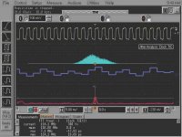
Reading this article (http://www.unitest.com/theory/jitter.html),
I have come across on interesting picture.
Upper curve - a clock pulses (456 MHz), blue histogram - a histogram of the point of the transition.
The blue line - TIE (Time Interval Error – TIE), red line - a FFT for TIE that is to say the jitter spectrum.
I have come across on interesting picture.
Upper curve - a clock pulses (456 MHz), blue histogram - a histogram of the point of the transition.
The blue line - TIE (Time Interval Error – TIE), red line - a FFT for TIE that is to say the jitter spectrum.
Attachments
Last edited:
-->Originally Posted by Xpertv
Is it necessary to add 2mA to TDA1541 outputs while I\U is provided by OpAmp? (Stock variant like NE5532\LM833) Or this is only for resistor I\U?
According to TDA1541 datasheet this is not required.
But if I/U is provided by opa-amp, accompaniment of 2 mA on output 1541 reduces the current through feedback resistor. This reduces the constant voltage on a opa-amp output (in ideal up to zero).
I have a nice Marantz DAC, TDA1541, and there we see separate 'channels' for the 2 mA bias current such that the I/V opamp is always at 0 volts, so no current feedback through the resistor; hence having an operating point with lowest distortion.
(apologies if I miss your point; Is this what you mean?)
albert
Is this what you mean?
Yes. Giving 2 mA on the opamp input, we install the zero voltage on the opamp output. This minimizes distortions.
What is the best method to inject 2 mA current to the DAC output? The Marantz solution is a 7.5k resistor from +15V. Here the cleanness of the PSU and the resistor noise could be an issue. Alternatively, a FET or transistor CCS could be used. Any other solution? Which is the best? What about thermal stability/drift?
What is the best method to inject 2 mA current to the DAC output? The Marantz solution is a 7.5k resistor from +15V. Here the cleanness of the PSU and the resistor noise could be an issue. Alternatively, a FET or transistor CCS could be used. Any other solution? Which is the best? What about thermal stability/drift?
Hi oshifis,
Im still using Johns old 2sk216 mosfet design from a while back now. When used in conjunction with a salus shunt im getting max drift of +-2mV on analog outputs.
While im at it - a quick question before i start trawling through this thread again. What was the cap value john is using from analog outputs to ground for the passive filtering? 2.2nF?
Ryan
What is the best method to inject 2 mA current to the DAC output?...What about thermal stability/drift?
The current generator can be built with use the current mirror or on FET. This is approximately equivalent alternatives.
The termal drift (in reasonable limit) is here not very important.
What is the best method to inject 2 mA current to the DAC output? The Marantz solution is a 7.5k resistor from +15V. Here the cleanness of the PSU and the resistor noise could be an issue. Alternatively, a FET or transistor CCS could be used. Any other solution? Which is the best? What about thermal stability/drift?
I have used a CCS (2SK170/200 ohm pot) [from plus 15 V; with a capacity multiplier in between] and that showed a small drift like about 2 mV slowly up and down; and of course I can't determine where it comes from. But 2 mV is quite acceptable of course!
One remark that I can't substantiate: I found this CCS solution to be a little brittle in sound, like an added harshness. But it can also be that I have just less second harmonics than I get with only a simple R for I/V - because the output generates seconds when not around zero. Question is what we like
alberthi everyone
I just want to tell my opinion of John's new sd1 sd player unit. I have used a buffalo dac for almost 2 year, a hifymediy sabre dac and a musical-fidelity V-dac.
None can even come close to the performance of the sd1 player.
Ive been listening to the sdplayer for 2 weeks now. I feel that I listen to the master tapes. The sound is natural in a way that you cannt find any default. The sound is totally transparent, detailed yet non fatiguing at all. The tone, the soundstage, everything is perfect really. I'm not good with those technicalities and words doesnt say anything. But everyday since Ive had it, I am amazed by every record. Jazz records I had heard a thousand time is revealing details, musical details that I had never heard. The little hi hats delicacy, naturalness is really amazing. I had never heard before such realistic highs, or such low bass. The impact of the bass, or the sub frequencies are stunning. I had never heard sub frequencies like that. They are like 3d. Im french, so my description really do not do justice, but damn this dac is exciting. I have never heard 10k dacs, but compared to anything I have used before, there is no contest.
The musicians, in some recordings, are really in my room. The depth of the soundstage is perfectly rendered, making the imaging so impressive. You can see how far the drums are to the piano. You could walk on the soundstage, almost.
The thing that I most enjoy about the dac, its the musicality of it. I dont know if its because of the dynamics, but its like you really understand the rapidity of the players. You really hear the musicians expressions, in a way its hard to explain. The timing between all the instruments is perfect. Its a totally envelopping musical experience because of this. This dac makes you listen to the music, you simply cannot care about the critical listening.
No matter what amp I use, either a tube amp, a cheap topping tp-20 class d amp, a headphone amp, a vintage marantz 2235b, its like the sdplayer cuts right through and you always get a amazing sound. The dac, I think, can suit anyone amp. I have also used the dac with my fonkens fe-127, dynaco a-25's, my 3-way, and thrue all of those, the magic was still there. The musical aspect never is hidden. Details, sure will be influenced by the elctronics, but the raw musicality never seem to be affected by the "system".
Sadly, I dont have a 10k vinyl playback system, so I cannot compare with a state of the art analog system nor a tape setup. I use a modified technic sl-1200 sitting on a suspension system with a stock arm and a denon dl-103. I use a opa627 op-amps phono stage modifed with the help of Thorsten Loesch. Anyhow, the sdplayer sounds better then my vinyl playback system overall.
I'm curious to know if theres other person in this forum who have bought the sdplayer and there impression...
Last edited:
Going to give NOS a try
Well you guys have convinced me to give this "NOS" with TDA1541A a try. So far I have pushed my 4X OS dac as far as I can really go. DIR9001/NPC SM5814/TDA1541A S1 single crown/ Pedja Rogic DDNF I/V / Passive filter flat to 20 Khz with 2nd order roll off. I'll post my thoughts. Dave BTW: Followed this thread for many years Thank you EC Designs!
Well you guys have convinced me to give this "NOS" with TDA1541A a try. So far I have pushed my 4X OS dac as far as I can really go. DIR9001/NPC SM5814/TDA1541A S1 single crown/ Pedja Rogic DDNF I/V / Passive filter flat to 20 Khz with 2nd order roll off. I'll post my thoughts.
Dave BTW: Followed this thread for many years Thank you EC Designs!the buffalo dac is considered one of the best kits around and I expected a "fair" comparison, not a total destruction.Calm down
All your other DACs had modern chips with oversampling.
Every nonos sounds better than that.
I personally never heard a buffalo or ess at home, only one friend had a V-DAC for a very short time, which was very poor even after modifications.
Calm down
All your other DACs had modern chips with oversampling.
Every nonos sounds better than that.
I personally never heard a buffalo or ess at home, only one friend had a V-DAC for a very short time, which was very poor even after modifications.
Hi Bernhard,
Would you have please a shematic to make a DAC with a single PCM56 ?
I never find on the net how to feed spidf to I2S then to a single PCM56. I have a CD player with a Toshiba 4052BP chip with a single PCM56. Maybe if you have a link or a ref for google I will be happy with that.
-sorry for this little () -
Hi MurphytheCat,
What chips are used for the buffer of the SD1 ?
Calm down
All your other DACs had modern chips with oversampling.
Every nonos sounds better than that.
I personally never heard a buffalo or ess at home, only one friend had a V-DAC for a very short time, which was very poor even after modifications.
bernhard!
why are you always so negative? you leave the impression that bad vibrations have somehow became your nature
... too sad actually!have you already heard/tested john's new sd1? if no, so please do not comment that way, even not in general! but if yes, so we would be very please to hear your opinion on the sd1 !
looking forward to reading anything supportive/constructive from you in this thread
best regards
mamal
- Home
- Source & Line
- Digital Line Level
- Building the ultimate NOS DAC using TDA1541A