Hi Audio curiosity,
Measuring results for some transistors used as zener diode (base and emitter).
2SC2240 9V5, 2SA970 10V8, BC547 9V, BC557 11V, 2N2905 7V3 2SA1360 10V, 2SC3423 7V6, MPSA44 9V4.
These zener voltages are too high to be used as reference voltage for 3.3, 3.6, and 5V shunt regulators.
However, this option is still interesting for the -15V supply. I also plan to test the LM329.
I have seen those measurements and that's one of the reasons I have been using LEDs as reference.
When you look at the schematics you will see that I already applied some LED noise filtering using 220uF electrolytic capacitor and 1uF film capacitor.
An idea might be to replace the LED by a low noise NPN transistor used as a Zener with collecter lead clipped off, base connected to negative and emitter connected to positive voltage
Measuring results for some transistors used as zener diode (base and emitter).
2SC2240 9V5, 2SA970 10V8, BC547 9V, BC557 11V, 2N2905 7V3 2SA1360 10V, 2SC3423 7V6, MPSA44 9V4.
These zener voltages are too high to be used as reference voltage for 3.3, 3.6, and 5V shunt regulators.
However, this option is still interesting for the -15V supply. I also plan to test the LM329.
More interesting info about LED noise (maybe mentioned before?):
I have seen those measurements and that's one of the reasons I have been using LEDs as reference.
When you look at the schematics you will see that I already applied some LED noise filtering using 220uF electrolytic capacitor and 1uF film capacitor.
Hi Tazz,
TDA1541A input capacitance (digital inputs) is specified at 12pF (Philips datasheet page 6).
The diodes basically limit signal amplitude to (Vin - 0.6) and +0.6V. So when using 5V TTL input signal, the output signal will swing between +0.6 and +4.4 (5V - 0.6V). Note that SD-player outputs 3.3V output signals. So the signal now swings between +0.6 and + 2.7V (3.3 - 0.6).
The TDA1541A works reliable with varying ambient temperatures when I2S signals swing between approx. +0.4V and +1.8V. So the existing circuit could cause problems at low temperatures (when TDA1541A is powered up cold). In this case the diodes in the TDA1541A input circuit have highest voltage drop and the input signal may fail to offer reliable latching.
Resistive attenuators in combination with TDA1541A 12pF input capacitance could lead to slow transients that could prevent reliable latching too.
The new SD-transport generates I2S signals (WS and DATA) with 1.8Vpp amplitude. I further reduce peak switching currents by using a series resistor (330R). The logic "0" threshold is lifted by a bias resistor between TDA1541A input and +1V8. This way the signal swings between approx. 0.4V and 1.8V, transients are still fast enough for reliable latching.
When the source generates 5V TTL level signals, it's best to use a 5V to 1.8V level translator for WS and DATA.
BCK is now generated directly by the timing module. The synchronous divider runs on 1.8V power supply, so it outputs approx. 1.8Vpp.
assume the 10pf is the actuall input capacitance of the dac you can see how much is injected into it.
TDA1541A input capacitance (digital inputs) is specified at 12pF (Philips datasheet page 6).
I think there might be room for some improvement with regard to the back to back diode solution.
The diodes basically limit signal amplitude to (Vin - 0.6) and +0.6V. So when using 5V TTL input signal, the output signal will swing between +0.6 and +4.4 (5V - 0.6V). Note that SD-player outputs 3.3V output signals. So the signal now swings between +0.6 and + 2.7V (3.3 - 0.6).
The TDA1541A works reliable with varying ambient temperatures when I2S signals swing between approx. +0.4V and +1.8V. So the existing circuit could cause problems at low temperatures (when TDA1541A is powered up cold). In this case the diodes in the TDA1541A input circuit have highest voltage drop and the input signal may fail to offer reliable latching.
Resistive attenuators in combination with TDA1541A 12pF input capacitance could lead to slow transients that could prevent reliable latching too.
The new SD-transport generates I2S signals (WS and DATA) with 1.8Vpp amplitude. I further reduce peak switching currents by using a series resistor (330R). The logic "0" threshold is lifted by a bias resistor between TDA1541A input and +1V8. This way the signal swings between approx. 0.4V and 1.8V, transients are still fast enough for reliable latching.
When the source generates 5V TTL level signals, it's best to use a 5V to 1.8V level translator for WS and DATA.
BCK is now generated directly by the timing module. The synchronous divider runs on 1.8V power supply, so it outputs approx. 1.8Vpp.
Hi marconi118,
TDA1543 and TDA1541A are based on CML (current Mode Logic). This offers much lower switching noise levels compared to TDA1387 and TDA1545 that are based on CMOS logic. CML maintains a constant current during switching (constant current sources), this offers very low switching noise levels. CMOS draws almost no current at steady state and peak currents during switching. This leads to high switching noise levels as current changes are now maximum.
Lower switching noise results in lower timing uncertainty at the D/A stage. This in turn leads to lower jitter levels at the D/A stage. Similar, the output signal remains cleaner as less noise is added to it.
This is one of the reasons why I still use the TDA1541A / TDA1543 and not CMOS based DACs that offer similar or better (THD) specs. Speaker distortion is always added to the DAC THD, so minimum THD will be around 1% when using high performance speakers and can increase above 10% when using average speakers. Similar, some of the LSBs are fully swamped by audio set distortion / noise. So even when using 64 bit digital audio source, practical resolution would remain well below 16 bits.
Given an optimized circuit where noise levels have been reduced to minimum practical levels. The limiting factor will then be jitter at the D/A stage and that is basically set by DAC chip properties.
They are 8pin and simple as the TDA1543 but with the 0v output compliance of the TDA1541.
It could be better sounding than TDA1543 but less complicated than TDA1541 DAC.
TDA1543 and TDA1541A are based on CML (current Mode Logic). This offers much lower switching noise levels compared to TDA1387 and TDA1545 that are based on CMOS logic. CML maintains a constant current during switching (constant current sources), this offers very low switching noise levels. CMOS draws almost no current at steady state and peak currents during switching. This leads to high switching noise levels as current changes are now maximum.
Lower switching noise results in lower timing uncertainty at the D/A stage. This in turn leads to lower jitter levels at the D/A stage. Similar, the output signal remains cleaner as less noise is added to it.
This is one of the reasons why I still use the TDA1541A / TDA1543 and not CMOS based DACs that offer similar or better (THD) specs. Speaker distortion is always added to the DAC THD, so minimum THD will be around 1% when using high performance speakers and can increase above 10% when using average speakers. Similar, some of the LSBs are fully swamped by audio set distortion / noise. So even when using 64 bit digital audio source, practical resolution would remain well below 16 bits.
Given an optimized circuit where noise levels have been reduced to minimum practical levels. The limiting factor will then be jitter at the D/A stage and that is basically set by DAC chip properties.
1) Similar, the output signal remains cleaner as less noise is added to it.
2) This is one of the reasons why I still use the TDA1541A / TDA1543 and not CMOS based DACs that offer similar or better (THD) specs. Speaker distortion is always added to the DAC THD, so minimum THD will be around 1% when using high performance speakers and can increase above 10% when using average speakers. Similar, some of the LSBs are fully swamped by audio set distortion / noise. So even when using 64 bit digital audio source, practical resolution would remain well below 16 bits.
3) Given an optimized circuit where noise levels have been reduced to minimum practical levels. The limiting factor will then be jitter at the D/A stage and that is basically set by DAC chip properties.
1) A simple test: 1 khz -60dB or - 80dB dithered sine wave displayed on a spectrum analyzer without averaging will show the noise floor. Comparison with other DACs will reveal the truth.
2) DAC related harmonics are always audible through speakers because of different spectrum.
In independent tests, TDA1541A totally failed in reproducing a LSB toggling signal, spitting out garbage, while other chips reproduced it flawless.
Resolution well below 16 bit is true for TDA but not for all.
3) Noise is less critical for listening than harmonics. Noise can mask detail but harmonics will alter tonal balance and can be disgusting.
Hi Bernhard,
It only shows performance of the DAC when generating 1 KHz sine wave. In practice the DAC has to generate many fundamentals plus harmonics simultaneously. The 1 KHz measurement doesn't show what will happen in this case.
In order to become audible, the harmonics must exceed certain threshold level so they are not masked by other (louder) signals.
http://www.diyaudio.com/forums/digital-source/113620-dac-linearity-test-cd.html
Post # 39 (oshifis):
"I tried this also on a Marantz CD-74 modified to NOS and digital filter bypassed. Here most bits are perfect or nearly perfect, except bit 9 which shows some oscillation-like noise on the bottom level, but not serious. Another reason for NOS?"
It seems like the garbage was caused by the SAA7220, not by the TDA1541A.
Philips datasheet spec indicates typical Edl of 0.5 LSB for a plain A chip. I have no reason to believe that Philips was not able to perform correct measurements.
When TDA1541A measured resolution turns out to be well below 16 bits, it is likely there is something wrong with the test setup / application.
Depends on how this noise interacts with circuit performance, think of masterclock or reclocker / divider power supply noise for example. Noise on the DAC chip logic power supply can also interact with on-chip logic circuits that in turn can lead to higher jitter amplitude and / or different jitter spectrum at the D/A stage.
1) A simple test: 1 khz -60dB or - 80dB dithered sine wave displayed on a spectrum analyzer without averaging will show the noise floor. Comparison with other DACs will reveal the truth.
It only shows performance of the DAC when generating 1 KHz sine wave. In practice the DAC has to generate many fundamentals plus harmonics simultaneously. The 1 KHz measurement doesn't show what will happen in this case.
2) DAC related harmonics are always audible through speakers because of different spectrum.
In order to become audible, the harmonics must exceed certain threshold level so they are not masked by other (louder) signals.
In independent tests, TDA1541A totally failed in reproducing a LSB toggling signal, spitting out garbage, while other chips reproduced it flawless.
http://www.diyaudio.com/forums/digital-source/113620-dac-linearity-test-cd.html
Post # 39 (oshifis):
"I tried this also on a Marantz CD-74 modified to NOS and digital filter bypassed. Here most bits are perfect or nearly perfect, except bit 9 which shows some oscillation-like noise on the bottom level, but not serious. Another reason for NOS?"
It seems like the garbage was caused by the SAA7220, not by the TDA1541A.
Resolution well below 16 bit is true for TDA but not for all.
Philips datasheet spec indicates typical Edl of 0.5 LSB for a plain A chip. I have no reason to believe that Philips was not able to perform correct measurements.
When TDA1541A measured resolution turns out to be well below 16 bits, it is likely there is something wrong with the test setup / application.
3) Noise is less critical for listening than harmonics. Noise can mask detail but harmonics will alter tonal balance and can be disgusting.
Depends on how this noise interacts with circuit performance, think of masterclock or reclocker / divider power supply noise for example. Noise on the DAC chip logic power supply can also interact with on-chip logic circuits that in turn can lead to higher jitter amplitude and / or different jitter spectrum at the D/A stage.
Dear John,
You convinced me to build your outstanding TDA1543 DAC with some modifications:
Battery PSU:
use alkaline batteries that have less noise than nicd or lead-acid
4X1.5v D cell in series direct supply to the +5V (it will be +6V but 1543 should survice)
Tap in the midle of the 4x1.5V series to obtain the 3V that goes to the I/V resistors. Or has it to be 3.2V exactly? maybe by changing the value of the I/V resistors (820R) it is possible to have 3.0V as the best bias reference?
Any advice on this?
It only shows performance of the DAC when generating 1 KHz sine wave. In practice the DAC has to generate many fundamentals plus harmonics simultaneously. The 1 KHz measurement doesn't show what will happen in this case.
You talk about the digital section of the DAC. And that similar, the output signal remains cleaner as less noise is added to it. Wether the measuring signal is 1 kHz or a "complex signal", doesn't matter much because there is always a number of bits switching from sample to next sample. The amount of parasitic energy depends on numbers of bits switching and MSB produces more trash than LSB.
Sample hold was used to suppress this energy with older chips that had bad settling time and produced spikes and other garbage. Same with the digital logic in the chip.
Even if it made a difference, when comparing two different chips, you can not expect that the results turn completely to the opposite when you change the measuring signal.
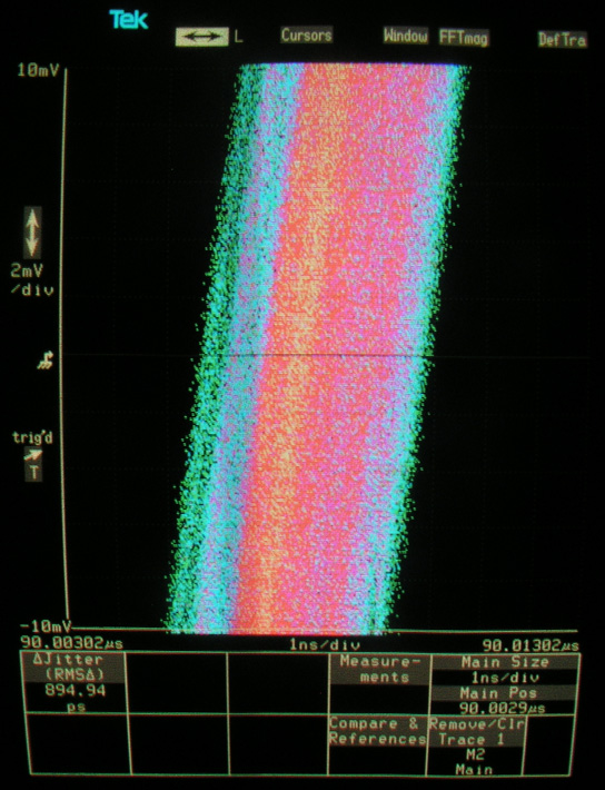
If I had to question one sort of audio measurement, I would name jitter measured with a analog scope.
One example of noise floor below.
In order to become audible, the harmonics must exceed certain threshold level so they are not masked by other (louder) signals.
I find this very questionable, but if it was true, the same would even more apply to noise.
http://www.diyaudio.com/forums/digital-source/113620-dac-linearity-test-cd.html
Post # 39 (oshifis):
"I tried this also on a Marantz CD-74 modified to NOS and digital filter bypassed. Here most bits are perfect or nearly perfect, except bit 9 which shows some oscillation-like noise on the bottom level, but not serious. Another reason for NOS?"
It seems like the garbage was caused by the SAA7220, not by the TDA1541A.
The Marantz CD-74 uses TDA1540.
He did the other measurement with a CD-94.
Yes, it is obvious that the oszillation/noise trash goes away when removing the oversampling.
But that does not mean it is getting better.
When you scroll down last page of that thread, you can see my measurements of -60dB signal with and without oversampling.
The horizontal line marks 60dB below the signal.
You can clearly see there is more noise with oversampling but less distortion.
Removing oversampling results in less noise but raises the harmonics.
Less noise without oversampling is in line with oshifi's observation.
My statement stands. The linearity of the 1541A is everything but good.
Maybe Philips added noise on purpose to mask harmonics. Nobody knows.
Other manufacturers used many tricks in the digital section to bring down low level distortion.
Which shows, they understood the importance of it !
Teac added digital noise to prevent the dac going below a certain analog level.
Later the noise was removed by canceling with an alternating noise only signal.
Clever people.
The cancellation had to be nulled with a pot.
That gave the opportunity to play around and listen to a noisy DAC.
I clearly preferred noise over harmonics.
Philips datasheet spec indicates typical Edl of 0.5 LSB for a plain A chip. I have no reason to believe that Philips was not able to perform correct measurements.
I do. IIRC the specs for the R1 version were better than for the plain A.
But it is well known that the R1 had relaxed specs.
Also, "typical" means, if your chips not hold up to their promise, they are sorry.
When TDA1541A measured resolution turns out to be well below 16 bits, it is likely there is something wrong with the test setup / application.
Please don't bother me.
I measured enough chips to know what I'm doing.
1541A low level performance is fair at best.
And this is, to use your own words: Highly critical.
Because it has exactly the same effect like crossover distortion in class B amplifier.
It gives unnatural sound.
I found a few good TDAs, sold them on ebay.
You say it yourself that there are better performing DAC chips:
This is one of the reasons why I still use the TDA1541A / TDA1543 and not CMOS based DACs that offer similar or better (THD) specs.
Speaker distortion is always added to the DAC THD...
Similar, some of the LSBs are fully swamped by audio set distortion / noise.
I can not agree.
So even when using 64 bit digital audio source, practical resolution would remain well below 16 bits.
If the chip performs like this from the start, yes.
Quote:
3) Noise is less critical for listening than harmonics. Noise can mask detail but harmonics will alter tonal balance and can be disgusting.
Quote:
Depends on how this noise interacts with circuit performance, think of masterclock or reclocker / divider power supply noise for example. Noise on the DAC chip logic power supply can also interact with on-chip logic circuits that in turn can lead to higher jitter amplitude and / or different jitter spectrum at the D/A stage.
I was not referring to jitter, (sorry if now jitter is your killer argument) but to what you say:
...similar, the output signal remains cleaner as less noise is added to it.
And you use TDA because you believe it has less noise than cmos. Maybe inside the TDA family.
Also you prefer the "quieter" TDAs over cmos that have better THD specs.
My opinion is very different. I believe harmonics are much more annoying than noise because they alter the tonal balance and add stuff that was not there before.
If you are on a holiday, what would you prefer ?
A hotel room close to the disco
or
a bungalow on the beach with noise from the sea ?
Same decibels.
Okay, you take the hotel room and I take the beach bungalow.

Have fun.
Last edited:
-ecdesigns-; said:Hi omainik,
AD1862 uses CMOS logic elements, and has no current steering / ECL like TDA154x. TDA154x I2S attenuator (200mVpp output) does not work here.
And here:
-ecdesigns-; said:Hi galeb,
No, (P)ECL gives too low output voltage swing to drive the TDA1541A. I use UHS buffers running on 1.8V power supply with series resistors on the inputs:
FAIRCHILD...
Now I'm a bit confused.
A DAC chip that runs on ECL, can not be driven by ECL ?
Last edited:
Bernhard, I read many of your threads and posts where you complain about the performance of various DAC chips. Please advise which DAC chip(s) you do like? It will be enlightening for all concerned.
Thanks
With my favourite PCM56, passive I/V is possible and 50% of chips have very good low level thd after adjustment.
Other DAC chips do not allow passive I/V, or 9 out of 10 have bad low level thd.
Maybe PCM61 or some AD chips like 1865 are an alternative.
I have no experience with modern chips because I stay with non oversampling.
Bernard, Though very OT by now, why did you not mention PCM63 or is that in your category of bad low level thd?
(PCM63 brochure) Funny what they say of the streaming bits at that time a hype.With PCM63P, the low-noise steps are clearly defined and
increase in near-perfect proportion. This performance is
achieved without any external adjustments. By contrast,
sigma-delta (“Bitstream”, “MASH”, or 1-bit DAC) architectures
are too noisy to even see the first 3 or 4 bits change (at
16 bits), other than by a change in the noise level.
With my favourite PCM56, passive I/V is possible and 50% of chips have very good low level thd after adjustment.
Other DAC chips do not allow passive I/V, or 9 out of 10 have bad low level thd.
Maybe PCM61 or some AD chips like 1865 are an alternative.
I have no experience with modern chips because I stay with non oversampling.
Hi Berhard,
This reminds me to inquire whether you have measured THD of the PCM1794A with passive I/V?
As you said, only a very few DAC chips are suitable for use with passive I/V. Most of these are 16-bit R-2R converters, but the 24-bit sigma-delta hybrid PCM179X series seems to be a contemporary exception. I believe that a number of commercial digital playback components use some version of PCM179X with passive I/V, typically of about 200 ohms on each output phase producing a FS signal of up to 1VRMS differentially.
The commercial digital playback components which I believe to utilize the PCM179X with passive I/V are: Audio Research CD-8, Ayre QB-9, Neko D100, and the Raleigh Audio RAKK DAC.
Last edited:
Bernard, Though very OT by now, why did you not mention PCM63 or is that in your category of bad low level thd?
(PCM63 brochure) Funny what they say of the streaming bits at that time a hype.
I think it has a clipping diode at the output and would need a high ratio transformer for passive I/V.
Also test results not overly impressing. Finding very good ones becomes expensive.
Hi Berhard,
This reminds me to inquire whether you have measured THD of the PCM1794A with passive I/V?
As you said, only a very few DAC chips are suitable for use with passive I/V. Most of these are 16-bit R-2R converters, but the 24-bit sigma-delta hybrid PCM179X series seems to be a contemporary exception. I believe that a number of commercial digital playback components use some version of PCM179X with passive I/V, typically of about 200 ohms on each output phase producing a FS signal of up to 1VRMS differentially.
The commercial digital playback components which I believe to utilize the PCM179X with passive I/V are: Audio Research CD-8, Ayre QB-9, Neko D100, and the Raleigh Audio RAKK DAC.
PCM1794A has oversampling inside.
In recent years I was very lazy but now I have a sampling scope with a horizontal resolution of 1ps/div and around 1ps intrinsic jitter.
Could help me to continue working on the digital section of my DAC.
I still have to get familiar with it.
This is 100kHz output from a "function generator":
PCM1794A has oversampling inside.
Yes, I know that the PCM1794A has an integrated OS digital filter - and, therefore, is not something one would consider for a NOS DAC project. Just the same, I was curious about how the PCM1794A THD performance measures via a resistor I/V because a few high-end digital vendors appear to be using it that way. Passive resistor I/V, while not uncommon in use with older generation 16-bit R-2R DAC chips is unique, to my knowledge, in use with the PCM1794A among modern 24-bit sigma-delta based DAC chips.
Last edited:
I think it has a clipping diode at the output and would need a high ratio transformer for passive I/V.
Also test results not overly impressing. Finding very good ones becomes expensive.
yes I have heard too the PCM63 has BAT-diodes to protect the output (the 1541 unfortunately has not, it costed me one at least in testing an I/V stage
). But an I/V with really low input (lower than John's 25-30 ohms of the 1/Idss of his 2SK170), say 2-4 ohms = less than 5-8 mV RMS will not be influenced by the remaining impedance of the diodes - this is my conjecture.
And I agree with your observation on the linearity, I saw that the PCM56's I had showed the LSB clearly; but the TDA1541 via the CS8412 will also shows the LSB clearly.
albertr
Hi John,
Interesting reading. I learned a lot here, thanks for that. It took me a while to read it though.
A few questions:
- Are the latest DAC schematics availeble? I couldn't find or have missed them.
- Is the DAC free to build? I prefer hardwire instead of PCB.
- I have a plain TDA1541 (non A). Can the DEM capacitor be neutralized somehow and is it possible to apply an external DEM clock at pins 16 and 17 instead?
- Could you tell me something about sound of a cryo treated TDA1541A? I know it works fine for tubes, so i'm interested.
- I live in the NL. Could i have a listen at your place?
Some ideas that i hope might be helpful:
- A balanced powersupply may result in about 20 to 30 dB additional interference noise cancelation. More information: Balanced Power (e.g. articles/widescreen.html).
I've applied this technique in my home build tube gear and cd player with great results. No more audible humm and noise, better definition, blacker background, more lifelike e.g. metal sounds etc. The TDA1541A specs dont show a balanced design, so maybe a balanced noise cancellation might be realised by using bleeder resistors and compensate the 'bleeding' power by choosing an equivalant higher VA rating etc.
- By removing (the upper layer of) the TDA1541A chip plastic and applying thermal conducting paste and a heatsink thermal distortion can probably be reduced. In my experience THD reduces also due to absence of plastic capacitance and better resonance suppression by the thermal paste. Needless to say the thermal paste needs to be electrical non conductice. I read something about removing the plastic housing in this thread. Did someone applied a stripped TDA1541A with some results?
- Beeswax and a wood center in coils can reduce small resonance en therefore distortion. Had some good results there in the past.
- Stripping capacitors form their plastic / aluminium housing and wrap them in paper, paint them with a natural varnish like 'schellak' or C39 and fixate them in a wooden (birch wood or enoby / blackwood sounds best imo) housing with beeswax can result in sound improvements. See also || DHTRob - Het modificeren van een electrlytische condensator (1) || (Dutch only, sorry)
- Jensen four pole capacitors after the bridige rectifiers sound qiute good. Better then blackgate WKz and way better than Sanyo Oscon imo. Expensive, around €70 each, but as for ultimate... See https://audio.jensencapacitors.com/products/
Henk
DAC sound
Hi John,
Thanks for giving me the oppertunity to drop by and listen to your DAC.
It sounds analogue and very lifelike. It's almost like listening to a live performance. I did'nt expect the absence of digital artifacts and had to get used to that, before i realised these artifacts were missing. I think this DAC is comparable with the best availeble in the market, and fyi i'm quite familiar with Audio Not DAC 2 and 3 with maximum modification and the Audiomagic DAC.
I learned a lot and hope to build my own DAC soon.
Henk
Three years after building my 4x 1541 s1 dac with input from John's thread....I am still finding some improvements and still just melt into my chair listening to it....
Recently I added a lot of SHIELDING between sections in my DAC. For example shielded the output from the rest...the power supplies...the linear intorpolation circuits...and on and on .....
Noise floor and jitter dropped...
What a great chip when you get it right....well almost right...I think some more shielding can help. It never really ends, does it....
JohnK
- Home
- Source & Line
- Digital Line Level
- Building the ultimate NOS DAC using TDA1541A