Hi Sir, about your octal DAC...
Now I recognize that is to late for say something, I Tried to read all the Forum posts about your creation, not only yours findings further the comments of the whole group, and the testimonial from another Dutch colleagues that listened your Frankenstein monster. Until discover this point of view about DAC non oversampling.
At the year 2000 I Build one DAC with four 1543 in Comodoro Rivadavia Argentina.
Since 2005 until now living in Europe more close to the technology after a lot of DACs i got, I am amazed with this topology and I need to try again. I understand that now i am servicing from your findings and your developments and like cook receipt I want to get all the info about it.
Do you have the whole project, schematics, pcb or at last pcbs for sale?
Thanks in advance for your generosity.
Esteban Bikic
dady@comodoro.com
Hi triode_al,
These are the crystals I bought:
CITIZEN AMERICA|HC49US11.2896MABJ-UB|CRYSTAL, 11.2896M, 18PF CL, HC49 | Farnell Nederland
They are specified at 11.2896 MHz and I received crystals with following printings: 11.2C76 and 11.2C63
Now I recognize that is to late for say something, I Tried to read all the Forum posts about your creation, not only yours findings further the comments of the whole group, and the testimonial from another Dutch colleagues that listened your Frankenstein monster. Until discover this point of view about DAC non oversampling.
At the year 2000 I Build one DAC with four 1543 in Comodoro Rivadavia Argentina.
Since 2005 until now living in Europe more close to the technology after a lot of DACs i got, I am amazed with this topology and I need to try again. I understand that now i am servicing from your findings and your developments and like cook receipt I want to get all the info about it.
Do you have the whole project, schematics, pcb or at last pcbs for sale?
Thanks in advance for your generosity.
Esteban Bikic
dady@comodoro.com
ECDesigns,
I am in AWE of the work you've put into optimizing your DAC. It is as clean and slick as any audio circuit I've seen with some truly unique and groundbreaking ideas!
Now after all that flattery, a quick question... I get that you don't select any of the components by 'accident'. But did you compare the Cornell-Dubilier acrylic SMD film caps to any of the other ones available like the Panasonic PPS?
Also, what were the best type of ceramics that you found for PS bypassing and can you say more about the issues you saw with them?
TIA!
Greg in Mississippi
The horn from the corner is Tanoy?
I see you live on Osorno, I had friends from this part of the planet and very good people I knew at Comodoro Rivadavia.
I come following this forum about the DACs (TDA 16bit) i just discover last week because i got a CD player with 1541 and look for some improvement in the peformance and found this monster blog. I made one DAC no oversampling 11years ago with four 1543 with receiver 8411 i guess, the circuit worked marvellous but i abandon for get more complex and modern ones. I started to read fast at the beginning but after two days I discover that this blog is an eternal source and fountain of wisdom, for this reason I restarted to read more carefully and become more tempting to re see or better, try to build one. I noted amazed in your pics the corner horn because i like full range speakers and horns.
Receive my regards from Spain compadre
Esteban Bikic
dady@comodoro.com
Hi Maxlorenz.Well, I am tweaking my DIDACs from DI16 and DI8x4 to DI4 or DI4x4...
On one of my DACs I added TeddyRegs for the output section (still LM4562, active IV) and the TeddyReg for the DAC chips was reduced to 5V (4,8 under load...).
Next (I hope this week) I will try the DATA and WS attenuators.
Apart, I got 220R SMD resistors for BCK...is it still OK, John?
I never asked this before, what is the reason to make the attenuator referred both to ground and to VCC? Has to be that the signal can be High or Low, right?
Is it OK if I put 22R in series to all signals from the timing chain???
I will show some picks of my test DI4.
Picasa Web Albums - mauricio - DIDAC
You can see the 4 Teddyregs...two for the DACs and two for the opamps. TeddyRegs rule!
Picasa Web Albums - mauricio - DIDAC
This one shows the mess with the PCB to adapt it...and DACs PS bypass caps arrangement. I increased 4K7 Rref to 18K...I still do not get the do-not-connect-it thing...
Advices are welcome...
Cheers,
M
Edit>
Sorry, double post while uploading images. Could the kind administrator delete the previous one?
I see you live on Osorno, I had friends from this part of the planet and very good people I knew at Comodoro Rivadavia.
I come following this forum about the DACs (TDA 16bit) i just discover last week because i got a CD player with 1541 and look for some improvement in the peformance and found this monster blog. I made one DAC no oversampling 11years ago with four 1543 with receiver 8411 i guess, the circuit worked marvellous but i abandon for get more complex and modern ones. I started to read fast at the beginning but after two days I discover that this blog is an eternal source and fountain of wisdom, for this reason I restarted to read more carefully and become more tempting to re see or better, try to build one. I noted amazed in your pics the corner horn because i like full range speakers and horns.
Receive my regards from Spain compadre
Esteban Bikic
dady@comodoro.com
hi dady,
The latest DAC module is the TDA1541A-MK8 with a single TDA1541A(S2). I posted concept schematics on this thread.
Power supply module still needs to be designed. I am currently testing pre-filtered common mode power supplies.
Do you have the whole project, schematics, pcb or at last pcbs for sale? Thanks in advance for your generosity. Esteban Bikic
The latest DAC module is the TDA1541A-MK8 with a single TDA1541A(S2). I posted concept schematics on this thread.
Power supply module still needs to be designed. I am currently testing pre-filtered common mode power supplies.
Hi Greg Stewart,
The components are selected for a specific application. Their effectiveness is verified by both measurements and extensive listening tests.
This depends on the application and there is no simple answer to it. I experienced problems with too high Q factor (NPO), piezoelectric effects and poor mechanical strength (caps often break in half when exposed to slightest mechanical stress).
Now after all that flattery, a quick question... I get that you don't select any of the components by 'accident'. But did you compare the Cornell-Dubilier acrylic SMD film caps to any of the other ones available like the Panasonic PPS?
The components are selected for a specific application. Their effectiveness is verified by both measurements and extensive listening tests.
Also, what were the best type of ceramics that you found for PS bypassing and can you say more about the issues you saw with them?
This depends on the application and there is no simple answer to it. I experienced problems with too high Q factor (NPO), piezoelectric effects and poor mechanical strength (caps often break in half when exposed to slightest mechanical stress).
I just reading the whole information of this blog and...
hi dady,
The latest DAC module is the TDA1541A-MK8 with a single TDA1541A(S2). I posted concept schematics on this thread.
Power supply module still needs to be designed. I am currently testing pre-filtered common mode power supplies.
I just reading the whole information of this blog and...
I started for the beginning (Always I must do that) Becoming more and more shocked for the project I abandoned nine years ago when I build a DAC with four TDA1543 and never listen again. After the page of this (the yours) if I remember near the seventieth one, you confessed that the another and more simple DAC sound better. Anyway this forum is for me a fountain of wisdom and knowledge, more than i can hold with my own capacity but anyway a challenge for learn a little bit more.
Please Sir if is possible to counsel about a paper for understand better DACs with the proposal of understand more deeply the title maybe must say "DAC for idiots in 24 lessons"
Thanks for your reply.
hi dady,
The latest DAC module is the TDA1541A-MK8 with a single TDA1541A(S2). I posted concept schematics on this thread.
Power supply module still needs to be designed. I am currently testing pre-filtered common mode power supplies.
I started for the beginning (Always I must do that) Becoming more and more shocked for the project I abandoned nine years ago when I build a DAC with four TDA1543 and never listen again. After the page of this (the yours) if I remember near the seventieth one, you confessed that the another and more simple DAC sound better. Anyway this forum is for me a fountain of wisdom and knowledge, more than i can hold with my own capacity but anyway a challenge for learn a little bit more.
Please Sir if is possible to counsel about a paper for understand better DACs with the proposal of understand more deeply the title maybe must say "DAC for idiots in 24 lessons"
Thanks for your reply.
Hi Maxlorenz.
I see you live on Osorno, I had friends from this part of the planet and very good people I knew at Comodoro Rivadavia.
I come following this forum about the DACs (TDA 16bit) i just discover last week because i got a CD player with 1541 and look for some improvement in the peformance and found this monster blog. I made one DAC no oversampling 11years ago with four 1543 with receiver 8411 i guess, the circuit worked marvellous but i abandon for get more complex and modern ones. I started to read fast at the beginning but after two days I discover that this blog is an eternal source and fountain of wisdom, for this reason I restarted to read more carefully and become more tempting to re see or better, try to build one. I noted amazed in your pics the corner horn because i like full range speakers and horns.
Receive my regards from Spain compadre
Esteban Bikic
Welcome dear Esteban,
Yes the speaker enclosures are the wonderful Tannoy Autographs from the 50's but the transducers are not real Tannoy but (spanish) Beyma 15"coaxials. I love them but they took me 4 months of my life to build them. I have a thread here with its story. I have the plans if you wish to: many members asked for them but no one reported back... The apparently also excellent P-Audio 15"coaxials are good replacement parts.
IMHO, horns are for classical music followers: never mind flatness of frequency response but look for speed or dynamics. My 10 year old child wanted a system for his room so I used USD30 tinny "surround" speakers that were lying there unused plus a trio of tubes (for an acoustic treatment project which name I forgot) and I installed them in a rear horn loaded bass:
https://picasaweb.google.com/lh/photo/evZRl6YWJxnPgEjkzoHp_dMTjNZETYmyPJy0liipFm0?feat=directlink
https://picasaweb.google.com/lh/photo/MBl9hLc8EsSepP14ovFxz9MTjNZETYmyPJy0liipFm0?feat=directlink
I kept them and lent my bookshelf to my son. Of course they are not perfect but they make sound instruments like real, even double basses. I will perfect the project with fullrangers and an exponential horn built from plywood.
I have 5 or 6 of John's DACs and I love them. The multiDAC chip DACs are god for party/jazz, having fuller warmer bass/midbass and the one DAC latest versions are cleaner and more defined, excellent for classical, though I have not yet the MK8 for which I am saving my pennies.
I abandoned the 4x4 DAC for power issues but I am considering it again as a passive and balanced out DAC, but I need to buy a scope for that.
The DIY honeycomb resistors are truly amazing. These DACs sound better the fewer the parts involved.
Good luck,
M.
Last edited:
Hi Maxlorenz
Thanks for your reply, Amazing horns, I just travelled for your blog and I will investigate for make one pair of them, I made at the end of 2005 (I need for glue them two month and half) one pair of horns, the cuts were so critic and they were make for a professional carpenter and I put a full range eight inches in and they are my favourites speakers. About the DACs maybe you have anything for sale, please tell me. You can email me in Castillan better to my address: dady@comodoro.com
I like opera and jazz to and valves amps and I will be glad in hear about you in Our predilection language.
To the rest of the fellows of the post my sincerely great salutations for the Christmas time with families and beloved people.
Power supply module still needs to be designed. I am currently testing pre-filtered common mode power supplies.
Well John.. we (I) are eagerly waiting...
Is it similar to the pre-regulator and capacitor multiplier parts of the schematic you posted earlier, which are then followed with a post-reg locally at the TDA ?
hi dady,
The latest DAC module is the TDA1541A-MK8 with a single TDA1541A(S2). I posted concept schematics on this thread.
Power supply module still needs to be designed. I am currently testing pre-filtered common mode power supplies.
Hi, John,
In briefly looking at your common-mode regulator (a need for which, I very much agree) it appears to me that it doesn't so much reject common-mode noise as it converts difference-mode noise into common-mode. Which would be great for circuits which inherently tend to reject common-mode noise, such as complementary symmetry, balanced circuits, and transformer-coupled circuits. Was that your design objective, or do you have a different view of what the regulator is actually doing?
Last edited:
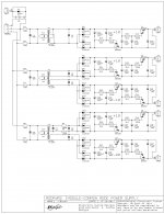
Common mode power supply schematics
Hi studiostevus,
This year I have been busy building a new workshop, so I had very little time for audio projects. This workshop has now been completed.
Yesterday I completed common mode power supply schematics and routing of the PCB. The module will hold 5 separate common mode power supplies and fits on a euro size PCB.
Capacitance multipliers are located on the power supply module, pre / post regulators are on the MK8 DAC module.
I attached common mode power supply concept schematics. When combining it with the MK8 schematics I posted earlier (post #4008 on page 401) you can see how I split up the power supply sections.
Hi studiostevus,
Well John.. we (I) are eagerly waiting...
This year I have been busy building a new workshop, so I had very little time for audio projects. This workshop has now been completed.
Yesterday I completed common mode power supply schematics and routing of the PCB. The module will hold 5 separate common mode power supplies and fits on a euro size PCB.
Is it similar to the pre-regulator and capacitor multiplier parts of the schematic you posted earlier, which are then followed with a post-reg locally at the TDA ?.
Capacitance multipliers are located on the power supply module, pre / post regulators are on the MK8 DAC module.
I attached common mode power supply concept schematics. When combining it with the MK8 schematics I posted earlier (post #4008 on page 401) you can see how I split up the power supply sections.
Attachments
Hi Ken,
Common Mode - attenuation to signals that appear identically on each of the wires going through the filter
Differential Mode - attenuation to signals that appear on just one of the lines.
Based on this, the new power supply should be called common mode power supply unless I am missing something.
Anyway, main function is placing a high impedance in both feed and return (GND). So the impedance between the mains and the powered circuit is high. With a conventional power supply, the return line (GND) has low impedance.
By placing a high impedance between mains and circuit, the effect of mains interference and ground loops can be greatly reduced.
Other objectives are very low noise, low output impedance and unconditional feedback stability under complex dynamic loading.
Was that your design objective, or do you have a different view of what the regulator is actually doing?
Common Mode - attenuation to signals that appear identically on each of the wires going through the filter
Differential Mode - attenuation to signals that appear on just one of the lines.
Based on this, the new power supply should be called common mode power supply unless I am missing something.
Anyway, main function is placing a high impedance in both feed and return (GND). So the impedance between the mains and the powered circuit is high. With a conventional power supply, the return line (GND) has low impedance.
By placing a high impedance between mains and circuit, the effect of mains interference and ground loops can be greatly reduced.
Other objectives are very low noise, low output impedance and unconditional feedback stability under complex dynamic loading.
Thanks John, very interesting!
I am currently running on Salas shunts, and playing around with the local decoupling of the power supply lines. What are your findings there? I see you only use a 1uF acrylic at the tda.
I have tried combinations of
-1uF acrylic smd
-22 uF BG STD
-270 uF Oscon SEPC
Not sure what I like best...
-22uF BG only --> seems like things are missing
-22uF BG + 1uF SMD --> added smoothness
-22uF BG + 1uF SMD + 270 uF Oscon --> Added bass
-1uF acrylic SMD only --> listening to it now, it seems very bass-heavy, but also liquidy smooth. I am not sure if I like the amount of bass... on the other hand it's quite analog now. It's less transparent though
What do you think?
Last edited:
I do tend to go a bit over the top at times & if you don't mind doing something quite ridiculous, add a couple more of those 1uFs in parallel to pins 13 & 18 so there is 4uF on them! I have 4uF of the Solen FCs there and I quite like the effect - no fat bass but quite heavy enough and very clean.
Also a bit outside the box, I've also got 2uF on all the other decoupling pins ...
The caps aren't particularly expensive but a bit more than 2 cents!
Also a bit outside the box, I've also got 2uF on all the other decoupling pins ...
The caps aren't particularly expensive but a bit more than 2 cents!
Just the 1uF of the Epcos caps - this one of mine is still pretty basic - a long way to go yet. Playing with EUVL's Cen o/p stage, etc and looking forward to trying John's new power supply design - love the humble C multiplier cct - use it on power amp supply rails sometimes.
- Home
- Source & Line
- Digital Line Level
- Building the ultimate NOS DAC using TDA1541A