Similar to the bias voltage used in Pedja's output stage (using 2sk170) I presume.
i didnt read properly... You are talking dc coupling. Pedja uses a bias for the tda's output current.
Hi Tazz,
If these caps indeed have 3uA leakage current, it is almost 50 times higher compared to the 0.061uA LSB current.
Problem is that the leakage current on the 6 MSBs (active dividers) won't be exactly the same and that the 10 LSBs (passive dividers) don't have this leakage current at all.
The result could be significant loss of (dynamic) resolution (up to 5 bits).
Looking at the TDA1540 schematic all the lesser currents are made to be accurate divisors of the MSB current any leakage on the MSB pin should only give an error in absolute magnitude since all lesser current are "automagically" rescaled to fit in with the MSB current.
I would expect the TDA1541A to be much the same with exception for the passive dividers but they also only divide further a divided down current.
Note however this would only be true for the MSB current as any leakage further down would put the larger currents off.
Could we hear a loss of 5 bits - or is it just measurable ?
It would sound as a telephone, I guess...
Young people listen music through mobile phones like if this was satisfactory...
Cheers,
M.
16-5 bits=11 bits dynamic range= 66dB. This is more that most Lp's, more than almost any commercial music, more than a typical SET amp. No it wouldn't sound like a telephone
I think it's absolutely fantastic what is being achieved with the good old TDA. The attention to detail and the obvious comprehensive understanding of the workings of this chip is at times quite breathtaking.
So, when I listen to my super clocked, valved, damped, independently powered and regulated, cap changed, diode upgraded, DEM re clocked TDA based machine....I just wonder how much better it can all get.
Then, having read the recent posts I now have to consider how much information I'm losing when you guys are worrying about 5 bits
Is anyone actually listening to these advances or are we just getting figures from scopes ?
This is in no way meant to sound rude. demeaning or ignorant.
I just wonder however what all this does to the sound of the TDA.
I'd like ecdesigns, galeb and maybe even studiostevus to tell us how wonderful it all sounds and then what happens to the sound when they make another big step in technical performance..
Am I being too simple here ?
I have not read the words ' bass, midrange or hf ' anywhere.
....and to Regal, what do we gain musically speaking by capturing 5 bits instead of losing them ?
Thanks
....and to Regal, what do we gain musically speaking by capturing 5 bits instead of losing them ?
Thanks
Dynamic range, I was mearly pointing out that losing 5 bits does not equate to telephone quality. If you have a good amp and well mastered recordings the difference should be very audible. If the 5 bits are really lost from dc leakage, I would think it would raise the noise floor, 11 bis would give a noise for of 66dB.
Guess what I am saying is caps leaking dc current does not equate to the 5 LSB, as those are AC currents, they have nothing to do with dc current leakage IMHO. The TDA1541 does have a 2ma DC offset and few microamps leakage thru the caps does not correlate to with the TDA1541's AC output (which is the music, the 16 bit resolution.).
Simply put the issue to bed, what is the noise floor of the design? I am guesing much better than -66dB.
The whole point of the internal architecture of the 1540/1541 is to accurately divide down a reference current. If you somehow affect this reference current and introduce some error all the lower bits will get rescaled by the dynamical element matching as well.
The caveat is this only works in one direction error introduced lower down in the chain will not affect larger currents and hence you will loose linearity.
The caveat is this only works in one direction error introduced lower down in the chain will not affect larger currents and hence you will loose linearity.
Again then...what comes out of the speakers when all these elements are covered ?
Is it nice ?
If I do all these things correctly is there yet more musical enjoyment to come ?
If I won the Lotto, I would go to ecdesigns website without hesitation and buy it all by the way....
Is it nice ?
If I do all these things correctly is there yet more musical enjoyment to come ?
If I won the Lotto, I would go to ecdesigns website without hesitation and buy it all by the way....
Hi Tazz,
Simple test will show if this doesn't affect bit accuracy. Connect a 1 M Ohm resistor between one of the active divider outputs and GND (simulating leakage current in one of the decoupling caps). Then measure / listen if this has no effect on sound quality.
Looking at the TDA1540 schematic all the lesser currents are made to be accurate divisors of the MSB current any leakage on the MSB pin should only give an error in absolute magnitude since all lesser current are "automagically" rescaled to fit in with the MSB current.
Simple test will show if this doesn't affect bit accuracy. Connect a 1 M Ohm resistor between one of the active divider outputs and GND (simulating leakage current in one of the decoupling caps). Then measure / listen if this has no effect on sound quality.
Last edited:
Hi John,
It depends on which active divider output you connect it to.
Ciao T
Simple test will show if this doesn't affect bit accuracy. Connect a 1 M Ohm resistor between one of the active divider outputs and GND (simulating leakage current in one of the decoupling caps). Then measure / listen if this has no effect on sound quality.
It depends on which active divider output you connect it to.
Ciao T
Hi AndrewGM,
This depends on the dynamic resolution of connected audio set, volume setting, ambient noise, and listening distance from the speakers.
Test signal (1 KHz, -60dB) is just barely audible when volume is set to maximum and when listening inches away from the speaker. With practical volume setting, listening few meters away from the speakers, masked by louder signals, in a room that isn't dead quiet, this test signal probably won't be audible at all. Test signal with 1 LSB change is probably inaudible at maximum volume setting in a dead quiet room listening inches away from the speaker. Air is used as transport medium between speaker membrane and auditory system, so its also in the signal path. Its properties like temperature, pressure and humidity will affect transport medium properties and the way we perceive sound.
So question remains how much LSBs can we still hear under practical listening conditions using practical audio equipment. I suspect that a loss of 5 bits would hardly be noticed under under such conditions.
Even if we had an audio set capable of maintaining true 16 bit dynamic resolution, ambient noises, even the heartbeat and breathing of the listener in the listening room could easily mask the LSBs.
But in practice, most audio sets fail to maintain even 8 ... 10 bits at practical volume setting, listening few meters away from the speakers.
The good news is that there is still lots of room for improvements ...
Could we hear a loss of 5 bits - or is it just measurable ?
If I could hear it - what would it sound like...
This depends on the dynamic resolution of connected audio set, volume setting, ambient noise, and listening distance from the speakers.
Test signal (1 KHz, -60dB) is just barely audible when volume is set to maximum and when listening inches away from the speaker. With practical volume setting, listening few meters away from the speakers, masked by louder signals, in a room that isn't dead quiet, this test signal probably won't be audible at all. Test signal with 1 LSB change is probably inaudible at maximum volume setting in a dead quiet room listening inches away from the speaker. Air is used as transport medium between speaker membrane and auditory system, so its also in the signal path. Its properties like temperature, pressure and humidity will affect transport medium properties and the way we perceive sound.
So question remains how much LSBs can we still hear under practical listening conditions using practical audio equipment. I suspect that a loss of 5 bits would hardly be noticed under under such conditions.
Even if we had an audio set capable of maintaining true 16 bit dynamic resolution, ambient noises, even the heartbeat and breathing of the listener in the listening room could easily mask the LSBs.
But in practice, most audio sets fail to maintain even 8 ... 10 bits at practical volume setting, listening few meters away from the speakers.
The good news is that there is still lots of room for improvements ...
Hi ecdesigns !!
..and thanks for taking the time with this explanation.
So I don't need to worry then...good
As a non technical person I'll have a go at most things if someone else says....' whoa... it makes such a difference to the mids an background detail ' etc
So when you ' clever guys ' discuss topics or your tweaks and findings I just kind of glaze over.
It's impossible to judge whether there is going to be a clear audible gain by experimenting with your ideas - plus...I don't want to SMOKE my TDA...
God knows I'm capable of doing just that
What I want you to say from time to time is something like.. ' if you try this the bass becomes more solid or recorded room acoustic becomes more audible '
Now that gets me started !!
Yep, I'm a bit too simple for this thread perhaps but I still want to get as much as possible out of my machine - just like everyone else here.
I have made good progress as a result of your posts and experience and I thank you for that....
Andrew
... But in practice, most audio sets fail to maintain even 8 ... 10 bits at practical volume setting, listening few meters away from the speakers.
The good news is that there is still lots of room for improvements ...
ecdesigns
Thank you for putting it all in perspective. Your research has moved the bar to new levels for all of us.
Putting the smt caps on the pins was a major improvement even if I used less than optimum caps. The impact on sound quality is quite startling. Hard to believe that a few mm can make such a difference.
I plan to replace them with your recommended film caps. Even if inaudible, having the highest possible signal to noise ratio is a good thing, and they will fit more securely in place. I'll report on sound impact of organic polymer vs film as a byproduct.
The polymer caps are likely well placed on the pins of power consumers.
Hi,
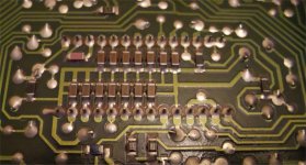
With the recent discussion regarding SMT caps for the active current dividers I thought people might be interested in the pcb layout Philips used in the CD630. Pin1 is bottom right.
Regards,
Jon
Interesting... Likely they used 100nf and they mounted them away from the pins. I also doubt they had the quality of caps we are using now.
Close but no cigar!
Hi JonHarrison,
It only looks better.
Power supply decoupling cap(s) ground share active divider decoupling cap ground. This results in power supply crosstalk on the 6 MSB currents.
Similar left and right channel active divider decoupling cap ground is also shared. This results in increased crosstalk between the 6 MSBs of left and right channel.
Finally digital ground > analogue ground current runs along the ground of all active divider decoupling caps. This ensures maximum interference on the active divider outputs.
The PCB GND traces are rather thin and are likely to have relatively high impedance (poor decoupling), this ensures even higher levels of unwanted crosstalk.
It's better to use separate GND returns for left channel decoupling caps, right channel decoupling caps and power supply decoupling caps. Both analogue and digital GND are best connected separately using a ground plane.
One has to pay very close attention to the GND return currents, making sure to keep all GND return currents well separated so crosstalk is minimized.
Theoretically a ground plane should also work here, but now all GND return currents still share one conductor and would introduce similar problems as with the Philips lay-out.
Keep in mind that PCB copper traces and planes are extremely thin, so resistance is much higher than expected.
I experimented with both, film and ceramic decoupling caps on power supply and active dividers. The perceived sound quality when using SMD film decoupling caps is a lot better compared to ceramic caps, possible cause could be ceramic cap piezoelectric effects and poor stability at varying temperature.
With the recent discussion regarding SMT caps for the active current dividers I thought people might be interested in the pcb layout Philips used in the CD630. Pin1 is bottom right.
It only looks better.
Power supply decoupling cap(s) ground share active divider decoupling cap ground. This results in power supply crosstalk on the 6 MSB currents.
Similar left and right channel active divider decoupling cap ground is also shared. This results in increased crosstalk between the 6 MSBs of left and right channel.
Finally digital ground > analogue ground current runs along the ground of all active divider decoupling caps. This ensures maximum interference on the active divider outputs.
The PCB GND traces are rather thin and are likely to have relatively high impedance (poor decoupling), this ensures even higher levels of unwanted crosstalk.
It's better to use separate GND returns for left channel decoupling caps, right channel decoupling caps and power supply decoupling caps. Both analogue and digital GND are best connected separately using a ground plane.
One has to pay very close attention to the GND return currents, making sure to keep all GND return currents well separated so crosstalk is minimized.
Theoretically a ground plane should also work here, but now all GND return currents still share one conductor and would introduce similar problems as with the Philips lay-out.
Keep in mind that PCB copper traces and planes are extremely thin, so resistance is much higher than expected.
I experimented with both, film and ceramic decoupling caps on power supply and active dividers. The perceived sound quality when using SMD film decoupling caps is a lot better compared to ceramic caps, possible cause could be ceramic cap piezoelectric effects and poor stability at varying temperature.
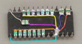
I attached a photograph of TDA1541A hardwired decoupling.
Red indicates +5V decoupling to AGND (pin 5)
Blue indicates -5V decoupling to AGND (pin5)
Purple indicates -15V decoupling to AGND (pin 5)
Yellow indicates left channel active divider decoupling to AGND (pin 5)
Orange indicates right channel active divider decoupling to AGND (pin 5)
Pins 4 and 5 are connected for convenience (pin 4 is nc on the TDA1541A).
Light blue indicates GND plane connection between DGND (pin 14) and AGND (pin5).
I performed some experiments connecting only the -5V (digital supply) decoupling to DGND, but listening tests showed a preference for decoupling to AGND.
With this wiring method, a local star ground is created at pin 4 / 5. This minimizes crosstalk between all connected GND wires as shared GND return paths are avoided.
Attachments
- Home
- Source & Line
- Digital Line Level
- Building the ultimate NOS DAC using TDA1541A