brubeck -
My bad! In the last posting I made, I said CARBON, I meant GRAPHITE. Sorry about that! Graphite resistors aren't readily available (Dueland (Denmark) has some, but they are physically huge. They can be made, here's an interesting article:
GRAPHITE RESISTORS
In any case, by the time you get to 500 ohms, they'll be big!
Gary
brubeck -
My bad! In the last posting I made, I said CARBON, I meant GRAPHITE. Sorry about that! Graphite resistors aren't readily available (Dueland (Denmark) has some, but they are physically huge. They can be made, here's an interesting article:
GRAPHITE RESISTORS
In any case, by the time you get to 500 ohms, they'll be big!
Gary
What is the diffrence between graphite en carbon composite? As fas as i know it's both carbon mixed with clay?
Have you ever tried writing with a resistor?
Seriously - the exact differences I do not know. I do know there are compositional differences in the balance of materials. It's know that CC resistors provide a more natural sound but can contribute more to noise. What I understand is that graphite has an open, airy sound with no noise artifacts.
You might want to check Duelunds website for more info. I may even take a stab a building some.
I bought the analog metric board on eBay. I sourced all the parts and assembled the board. The static voltages all check out. I am using the CS8414. On page 11 a note says R25 should be 1k ohms and c33 should be 68nF, c35 should not be installed. On page 4 of the instructions, the following can be found:
Either uses 1K ohm for R25, 0.047uF for C33 for CS8412.
Do not assemble C35; R25 = 470ohm and C33 = 68nF for CS8414 Or Use 470 Ohm
for R25 and 0.22uF for C33, 3300pF for C35.
I get nothing on pin 26 of cs8414 whether or not a digital signal is present on the RCA input. Also what should the signal look like on pin 9 of cs8414. I'm getting no output. I don't see anything on the data and have no idea where the signal is being lost. This board is the biggest waste of time and money I have ever experienced. Has anybody ever been able to get this piece of junk working in either oversampling or non-oversampling mode?
Have you ever tried writing with a resistor?
Seriously - the exact differences I do not know. I do know there are compositional differences in the balance of materials. It's know that CC resistors provide a more natural sound but can contribute more to noise. What I understand is that graphite has an open, airy sound with no noise artifacts.
You might want to check Duelunds website for more info. I may even take a stab a building some.
I did some listening tests with MK7 DAC using different carbon composite resistors direct in serie with the DAC output signal. Tried 1 to 15 ohms and several watts (1/4, 1/2 and 1). If i can believe my ears the effect of more noise is significant. To much noise masks the sound immediately. In my setup i ended up with a 4,7 ohm 1/2watt. Just enough to add some sonic cream without causing masking effects.
I did some listening tests with MK7 DAC using different carbon composite resistors direct in serie with the DAC output signal. Tried 1 to 15 ohms and several watts (1/4, 1/2 and 1). If i can believe my ears the effect of more noise is significant. To much noise masks the sound immediately. In my setup i ended up with a 4,7 ohm 1/2watt. Just enough to add some sonic cream without causing masking effects.
A little rectification has to be made after further listening. With very good recordings, even 4,7 ohm gives little masking effects of the LSB's. (bravo for the resolution of the MK7 DAC!). With older recordings the resistor smoothens the sound in a gentle way. (i have to make a switch ;-)
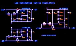
Here are the schematics of +5V, -5V and -15V LED-referenced series regulators with integrated capacitance multiplier for the TDA1541A. Exact output voltage can be set with R3, R8, and R12 (higher value increases output voltage, lower value decreases it).
The circuit works as follows (using +5V schematic as reference):
R1 and C1 form a low-pass filter that attenuates ripple voltage. R2 feeds the cleaned-up DC voltage to Darlington T1, driving it into saturation. C2 provides frequency compensation.
The output voltage is divided by R3 and R4, and connected to the base of T2. T2 emitter is connected to a green LED (approx. 2V).
As soon as the voltage across R4 exceeds 2V + 0.6V (V-BE), T2 starts conducting, reducing the current flow through T1. This way the regulator settles around the required output voltage.
If R4 was removed from the circuit, output voltage would settle around V LED (2V) + V-BE (0.6V) = 2.6V.
The circuit responds very fast (minimum delays), and noise levels are low enough for audio applications.
The LED could be replaced by suitable low-noise zener diodes, but do carefully check effects on sound quality.
Keep in mind that the noise produced by the reference diode is amplified by the attenuation factor of the voltage divider. With the 5V regulator, the LED noise is amplified approx. 1.9 times.
With the -15V regulator LED noise is amplified by approx. 2.7 times.
So try to find an optimum between reference diode noise and voltage divider properties.
The voltage drop across LEDs with different color are slightly different:
Current = 20mA.
Infra-Red LED, approx. 1.3V
Red / Orange LED, approx. 1.9V
Yellow LED, approx. 2V
Green LED, approx. 2.1V
Use plain LEDs (no low current LEDs) for lowest noise. Don't use blue or white LEDs.
I used green LEDs for these voltage regulators as they provide highest voltage drop (2V).
Hi,
Thankyou for the wonderful contributions here ecdesigns.
Just wanted some clarification with regards to your led ref supplies.with the -15 volt suppy r9 and r10 are 6k8 in one diagram and 2k2 in another...does matter which i use there?Also can c26 100uf be bigger..say 330uf?
thanks again
Paul
Attachments

Hi Brubeck,
So what carbon 'composite' resistor are you using?
Maybe you could try a carbon 'film' like a Riken-ohm or a Kiwame/KOA which will have less noise (masking) than a 'composite' resistor...
Peter
See post #3701
Thanks for the tip. The 'harmonizing' effect is imo not only affected by the structure of graphite/composite but also the current and value. It's a hard part to quantify the effect. Trail and error...
Hi John,
I don't know if you are aware of this thread - http://www.diyaudio.com/forums/digital-source/30025-decoupling-tda1541a-11.html
In post 2738 of your thread you discuss the MSB/LSB current switching in relation to the DEM clock frequency and suggest different decoupling capacitor values for each pair of pins but your Mk.4 DAC uses 47nF and the Mk.7 uses 1uF on every pin. I would be grateful if you could help me to understand which method of decoupling is correct and how to calculate the correct values to use. Is the MSB capacitor chosen to have minimum impedance at the clock frequency and then the remaining capacitors are scaled down according to the current-charge/discharge time on that element ?
Regards,
Jon
Tuning the capacitor is the easiest way for lowering DEM clock jitter amplitude, but jitter won't be as low as with an low jitter external DEM clock (DEM clock oscillator intrinsic jitter). So this modification improves sound quality over the 470 or 680pF, but still isn't optimal.
So, for the first test 250pf DEM cap for 352.8khz - 4 x oversampling @ 44.1 ?
When the DEM clock capacitor is removed, the DEM clock oscillator will run on stray capacitance (few pF), and produces a clock signal of around 7 MHz. By removing the capacitor and connecting these terminals to -V (-15V), using 2K2 resistors, oscillation stops. Now the external clock signal can be injected through 2 x 10 K Ohm, basically toggling the oscillator circuit with the external 352.8 KHz differential DEM clock that is derived from the low jitter master clock.
and the second test - do the above and feed a 2.8mhz clock feed to which pins... 16 ?
If so, what do I do with the 17 ?
Apologies if I should already have understood this - it's just dawning on me now
Thanks
Hi John,
I don't know if you are aware of this thread - http://www.diyaudio.com/forums/digital-source/30025-decoupling-tda1541a-11.html
In post 2738 of your thread you discuss the MSB/LSB current switching in relation to the DEM clock frequency and suggest different decoupling capacitor values for each pair of pins but your Mk.4 DAC uses 47nF and the Mk.7 uses 1uF on every pin. I would be grateful if you could help me to understand which method of decoupling is correct and how to calculate the correct values to use. Is the MSB capacitor chosen to have minimum impedance at the clock frequency and then the remaining capacitors are scaled down according to the current-charge/discharge time on that element ?
Regards,
Jon
That's a good question too - didn't notice the 1uf's.
There were also 9 frequencies offered with obviously 9 DEM capacitor values for a successful ' lock ' to BCK for lower jitter amplitude - compared to 470 and 680pf caps generally used.
How do I calculate which one to go for for 16x4 oversampling - 44.1
Thanks
Andrew
Common mode cap multipliers fro higher currents
Hi EC designs,
I am fascinated by your circuit for common mode cap multipliers to reduce noise before using a regulator. Presume this will be OK only for about 100ma or so.
Any suggestions for transistors that can be used for higher currents such as 1 to 2 amps?
Can this also be extended to higher voltages say 300 to 350V used in tube pre- amps? I am currently using a solid state regulator put up on Gary Pimm's page called the Swenson regulator. I suspect that if adapted the same advantages may accrue.
Any way, thanks for sharing these great ideas.
Cheers!
B.Ravi
Sorry for the delays answering emails and questions on this thread, I am currently building a new workshop that will include a dedicated listening room for testing. I am (trying) to build it all by myself.
Hi bravi,
BD679 / BD680 Darlingtons are rated at 5A and 40 watts, so higher currents are no problem. However, Darlington base current needs to be increased (base resistor value reduced), this in turn requires increased capacitor value for the capacitor between Darlington base and reference (GND).
It is also possible to compose a Darlington using separate transistors for higer current / voltage rating.
Yes, no problem, it would also be very suitable for achieving ultra low ripple voltage on direct heated filaments like the A300B for example. It should be possible to construct a tube (pre) amp this way that produces no audible hum, just the noise from the tubes.
Hi bravi,
Hi EC designs,
I am fascinated by your circuit for common mode cap multipliers to reduce noise before using a regulator. Presume this will be OK only for about 100ma or so.
Any suggestions for transistors that can be used for higher currents such as 1 to 2 amps?
BD679 / BD680 Darlingtons are rated at 5A and 40 watts, so higher currents are no problem. However, Darlington base current needs to be increased (base resistor value reduced), this in turn requires increased capacitor value for the capacitor between Darlington base and reference (GND).
It is also possible to compose a Darlington using separate transistors for higer current / voltage rating.
Can this also be extended to higher voltages say 300 to 350V used in tube pre- amps? I am currently using a solid state regulator put up on Gary Pimm's page called the Swenson regulator. I suspect that if adapted the same advantages may accrue.
Yes, no problem, it would also be very suitable for achieving ultra low ripple voltage on direct heated filaments like the A300B for example. It should be possible to construct a tube (pre) amp this way that produces no audible hum, just the noise from the tubes.
In post 2738 of your thread you discuss the MSB/LSB current switching in relation to the DEM clock frequency and suggest different decoupling capacitor values for each pair of pins but your Mk.4 DAC uses 47nF and the Mk.7 uses 1uF on every pin. I would be grateful if you could help me to understand which method of decoupling is correct and how to calculate the correct values to use. Is the MSB capacitor chosen to have minimum impedance at the clock frequency and then the remaining capacitors are scaled down according to the current-charge/discharge time on that element ?
In order to prevent inter-modulation between free running DEM oscillator and I2S timing signals (inter-modulation occurs through on-chip crosstalk and EMI) it is required to have DEM clock running fully synchronous with I2S timing signals. Similar applies to presence of external clocks used to drive remote control, display, network communications and so on. It is best to drive the DAC and all circuits connected to it using one single masterclock.
If extra oscillators are required for remote control for example, the oscillator(s) should be shut down immediately after a command has been executed. New commands should initiate an interrupt that temporarily wakes chip and oscillator.
After testing various DEM injector circuits I ended up using balanced DC-coupled DEM synchronizer feeding a differential DEM clock into pins 16 and 17. The 2K2 resistors to -15V and the 10 ... 12K resistors and Schottky diodes to the clock source provide required bias voltage on pins 16 and 17, the diodes provide temperature compensation. The value of the 10 ... 12K resistor is critical and may need to be tuned / optimized to the DAC chip due to tolerances.
I use 2.8224 MHz ultra low jitter DEM clock in the MK7 DAC, it is generated by a shift-register divider that divides the masterclock frequency by 4. It's based on the fastest CMOS flip-flops I could find, ground-bounce compensation and clock load reduction circuits were used to maintain lowest possible jitter.
Listening tests showed that resolution and refinement increases as DEM clock frequency is increased.
Decoupling cap main function is RF decoupling while maintaining lowest possible DC leakage current.
In the MK7, Cornell Dubilier RF film decoupling caps were used (1uF / 16V / 1210 size). They were mounted on the side for further inductance reduction. The decoupling caps are mounted underneath the DAC chip using shortest possible traces. Since minute interference currents can have direct effect on dynamic bit accuracy by modulating voltage on decoupling cap GND reference, it is very important to use separate GND return path for these decoupling caps. Even a non-interrupted ground plane can't prevent ripple voltage on decoupling cap GND reference.
When using large capacitors with leads, placed around the DAC chip, RF decoupling is basically non-existent. Every millimeter counts and capacitors with wires are very much worse for RF decoupling than miniature SMD film caps specially designed for RF decoupling. Advantages of SMD film caps are low leakage current, low inductance, and no piezoelectric effect.
I used 47nF in earlier designs until I found the 1uF versions from Cornell Dubilier. The idea is to filter active divider switching noise to lowest possible practical level.
When using different decoupling capacitor values, leakage current properties and inductance will vary too. This could increase bit errors by introducing different leakage current on each active divider. So I advise to use same capacitors for all decoupling pins.
Just to get an impression of leakage current impact, LSB corresponds to 61nA, in order to maintain 1/4 LSB, DC leakage current should not exceed 15nA. The DC voltage on the decoupling pins is around -9V on average, this translates to a resistor value of 600 Mega Ohms!
Hi John, I have just taken 5 days to read through the full thread. It was actually very interesting to read the development of the dac from DI8 to mk7 over 5 years.
I have a tda1541a dac based on Oliver's boards at home, and looking for ways to improve it. I have some questions that are not clear yet to me:
1. What happened to your shift register / one-shot solution for reclocking USB? I read it disappeared since it still generated too much jitter compared to an integrated SD-card solution, but would it still be your preferred solution for working with USB? I am planning to use a mac mini as transport, for simple reasons of GUI and flexibility and looking for the best sounding solution given this transport.
2. You have created many inventive solutions that would be applicable to your earlier models as well (DI8 and DI4). What would happen if you implement the latest DEM, DJA, discrete shunt regs, simplistic output stae, honeycomb resistors, masterclocking, etc. to those models?
3. What is your view on balanced setup with 2 dacs? (R+/R- on one chip, L+/L- on the other) ?
4. I read somewhere that mk6 or mk7 would be your last model based on one tda1541. Later I read that you implemented a certain circuit for 'compatibility reasons with modern dacs'. What does the future have in store for us?
Thanks very much for your time, and keep up the good work. It has been very informative!
Maybe my question was too simple for consideration.........
Anyway, I chose 352.8mhz as a ' shot in the dark ' and have now fitted a 250pf 2% tolerance silver mica capacitor across pins 16 an 17.
If I can find a 1% tolerance cap in the future I'll swap them out.
It works - I like it - it sounds better than 470 pf styrene.
Anyone interested in trying this cheap tweak will be pleased with the results.
- Home
- Source & Line
- Digital Line Level
- Building the ultimate NOS DAC using TDA1541A