Synchronous reclocking with TDA1540
I completed a pcb with four 74AUC1G74 flip-flops (I need two DATA as TDA1540 is mono), all are supplied at about 2V, but it doesn't work. I'm only able to get the BCK 74 working (but only bypassing the 1K output resistor and connecting pin 3 directly to DACs). I tried to bypass both 2K2 and 1K resistors on DATA and WS signals, but that didn't help. Then I connected directly the two DATA signals and reclocked the WS only, but I only got noises with very distorted and low music. Thinking that one 74 could be dead I moved the WS on the other two (and also an external, flying, one) with no success. Connections are correct, I checked them so many times, and now I don't know what to think or to do. Maybe this circuitation is not compatible with the old 14 bit Philips chipsets (SAA7000), but since years I use the SAA7000 I2S output connected only via 100R resistors to the TDA1540 with no oversampling (SAA7030 removed).
Thank you for any suggestion.
Last edited:
Hi fvale,
Check if power supply is ok (2.4V), also check if signal levels are suitable to drive the TDA1540.
You may have damaged one or more reclockers by overheating or by applying too much force during soldering, these tiny chips are rather fragile.
If power supply and signal levels are ok and the circuits still don't work you may need to check exact moment of triggering in your application. If the reclockers are triggered on the wrong moment they don't sample the correct signal level. You may need to invert / delay the clock signal for the synchronous reclockers.
The clock signal on the reclockers should change when BCK, DATA, and WS signals are stable. The clock signal should not change during signal transitions of BCK, WS and DATA.
Thank you EC for immediate support!
First of all my power supply (it's only dedicated to five 74AUC1G74s, one is also used to get my main 4MHz clock from a 8MHz oscillator) delivers 2.06V under load. May this be the problem? Tomorrow I will have to replace a zener diode to get 0.3V more.
I only have a simple handy multimeter that also work as a basic frequencymeter. What can I check with that? Thanks again.
I also thought about the possibility of flip-flop damage, but it's strange that four are dead. Problem should be elsewhere.
Hi fvale,
You can check if clock signals are present (if the reclockers output a signal), but not much more. In order to spot and solve timing issues a suitable analogue oscilloscope is required.
I advise a (second hand) Hameg dual channel analogue scope (2 x 20 MHz or higher).
Have a look here:
Hameg Oscilloscopes | The Oscilloscope Shop
This one looks interesting:
HAMEG HM203-7 Oszilloskop Oscilloscope Oscilloscope 203 - eBay, Oszilloskope, Mess- Prüftechnik, Elektronik Elektrotechnik, Business Industrie. (Eindtijd 12-feb-11 14:03:32 CET)
I only have a simple handy multimeter that also work as a basic frequencymeter. What can I check with that?
You can check if clock signals are present (if the reclockers output a signal), but not much more. In order to spot and solve timing issues a suitable analogue oscilloscope is required.
I advise a (second hand) Hameg dual channel analogue scope (2 x 20 MHz or higher).
Have a look here:
Hameg Oscilloscopes | The Oscilloscope Shop
This one looks interesting:
HAMEG HM203-7 Oszilloskop Oscilloscope Oscilloscope 203 - eBay, Oszilloskope, Mess- Prüftechnik, Elektronik Elektrotechnik, Business Industrie. (Eindtijd 12-feb-11 14:03:32 CET)
Last edited:
Hello EC,
I knew that one day I had to buy an oscilloscope..... it was today! I just bought one at the link you suggested on ebay. They accepted my 110 Eur offer! Not bad!
Update: leaving only BCK on the smd 74 I connected a flying 74HC74 on WS. Again no success. I suspect all flip-flops to be ok.
With my tester I measured frequencies on flip-flop's pins 2 and 3. On BCK I can read 44.1Khz (????, I expected about 1MHz frequency with MCK ay about 4MHz) both at input and output. On WS I read 44.1Khz on input pin 2 but NO signal on pin 3. This happens both with smd or dip 74. Another think I noted is that on output pin 3 (again both smd and dip) I see a DCV respectively of 2V with smd and 5V with dip. This is flip-flip powering tension. Is this normal?
Many thanks!
Yesterday I tested another 3 74AUC reclockers with a different I2S source (Squeezebox receiver) and this time all works perfectly. I only had to bypass the 1k output resistor on WS.
Then I went back to the 14 bit Revox player. First of all I singularly checked all flip flops as frequency dividers: they all worked regularly. I made a further test, but results are the same of the first time. Only BCK can be reclocked succesfully.
Let's wait for the scope...
Then I went back to the 14 bit Revox player. First of all I singularly checked all flip flops as frequency dividers: they all worked regularly. I made a further test, but results are the same of the first time. Only BCK can be reclocked succesfully.
Let's wait for the scope...
THX! Looking forward to building it! And then to hearing it
Cheers Ernst

Hi ernesternest,
did you manage to build and tested mini regulators?
When you will once hear them, you will want to get rid of all standard LM... regulators.
Mine is now in Mk4 version and it is make quite big step in sound quality (more pure, ...).
I just want to taste them, since i am waiting list for final MK6 version.
")
Bostjan
Hi ernesternest,
did you manage to build and tested mini regulators?
When you will once hear them, you will want to get rid of all standard LM... regulators.
Mine is now in Mk4 version and it is make quite big step in sound quality (more pure, ...).
I just want to taste them, since i am waiting list for final MK6 version.
Bostjan
Bostjan,
I have parked this project for a while since my sparetime is currently very limited (preparing for building my own house) What I tried is to design a PCB for the regulators right after Johns pictures. Wanted to do this in Eagle, but stopped since I couldn't find all the footprints needed. To be honest, I have no plan how to carry on. PCB would be great, since parts are available. Currently I'm waiting for the semiconductors for MK6 outputstage. Will use Teddyregs and/or Salas shunts until I managed to make/get pcbs for the regs. i have some nice old CDPs, they are all waiting for these regs, since they are a real drop in replacement for the unwanted 7XXX regs.
Cheers Ernst
Hi maxlorenz,
Thanks for your reply,
The HDD "quality" doesn't matter at all here, since data is first buffered in RAM (Random Access Memory). When you play music trough a pc / mac, you are basically reading it from a semiconductor memory rather than a HDD. The HDD only fills the RAM buffer, it has plenty of time to do this. SATA connection stands for Serial ATA, it's a serial interface type that allows for faster data transfers.
To avoid quality loss, use either WAV or some type of lossless compression. WAV files take up more HDD space than the ones using lossless compression.
I use a mac music player with the Apple Lossless format. With ubuntu you could use flac lossless compression. There are many other different lossless formats like ALAC, FLAC, LA, LPAC, APE, MPEG-4 SLS, OFR, RAL, SHN, TTA, VW, WMAL and ADA.
Before you start storing CD images, it's a good idea to pick the lossless compression format that's best suited for the application you intend to use.
With better power supply, you could think of a higher quality power supply with a very silent cooling system. Most cheap pcs have crappy power supplies that are just capable of supplying enough current.
The pc motherboard caps are a different story, it seems at some time electrolytic capacitors with wrong electrolyte where used. These caps pop-open and loose their capacitance over time. It starts with a lot of high-pitched noise from the motherboard DC converters, and start-up problems. In the end both power supply and motherboard could fail. If you have a pc motherboard with these electrolytic capacitors, it's a good idea to replace them before they could cause problems.
You could also use high quality caps / decoupling close to the USB connector power supply (5V), so the connected USB / I2S / SPDIF devices receive a cleaner power supply.
Use System > Administration > network.
Ubuntu usually detects everything fully automatic, (I am using the latest Feisty Fawn version). If the internet is not "recognized" automatically, you may need to add a router.
What I also meant is that the DI 16 manages to provide similar sound improvements on completely different audio sets.
As for interlink materials / constructions, these both do have significant effect on sound quality. Interlinks need to transport ac signals without over-emphasizing different frequencies (flat frequency response). This is much more difficult than most people would think. Interlinks have a specific inductance, Eddy currents cause frequency-dependent losses in the interlink material, and conductive materials placed close to the interlink.
Eddy currents could also cause a lot of problems is speaker crossovers, and sound quality is accordingly.
Hello John
Would these newer media transports such as WD Mini , Popcorn Hour C-200 etc etc (they use realtek and Sigma based integrated CPU/GPU) Would they be any good to use a transport compared to a fully optimised PC ?
Regards Paul
Hello John,
Some questions about your latest schematics, the Mk6 version. It's fun to follow your progress, constant changes, never boring.
1. You did use extreme LC-filtering for the oscillator, up to 20:th order or something, and now just a 40 ohm, resistor, quite a change, why !?
2. This 40ohm, with 1uF will give approx. Fc of 4kHz. It is the same 5V feeding the 500ohm output resistor. Are you not modulating the oscillator with the analog output?
2. The flip-flops for WS, MCK, DATA are now feed by a 680ohm or 1.5k resistors from 5V, how does this work ?
4. 1uF ceramics for decoupling everywhere, analog as well as digital?
(except the 47nF's for the TDA1541)
//Per
Hi phi,
This filtering was an attempt to get rid of 78XX regulator large bandwidth noise. It didn't help much, once the interference is generated it is almost impossible to fully block it. So I tackled the problem by the source by using high resolution, large bandwidth, ultra low noise discrete voltage regulators.
All bit currents (current flowing through passive I/V resistor, and unused bit currents) flow back into +5V. The MK6 has no active output stage, the output voltage is generated across a 500 Ohm I/V resistor. The power amp "measures" the ac voltage across this I/V resistor. This means that ripple voltage due to the audio signal is extremely low and no problem for the masterclock.
The RC filter offers sufficient attenuation of the 11.2896 MHz clock signal. The 40 Ohm Mobius Honeycomb wire wound resistor adds very little noise, so inter-modulating noise spectra are minimized.
The +5V power supply is taken out of the signal path as I use +5V (or a derived voltage) as reference. The TDA1541A keeps the output current through the passive I/V resistor constant (high PSRR). So we basically have a clean ac voltage across a 500R passive I/V resistor, even if the +5V power supply would be a bit noisy.
I used these resistors in order to provide high series impedance over a very large bandwidth while keeping the circuit as simple as possible. Ferrite beads have problems with core saturation (DC current) and hysteresis.
The reclockers drive I2S attenuators, design is such that the reclocker only has to drive little over 12pF load. The signal amplitude equals 1.2Vpp instead of the usual 5Vpp. This not only reduces ground-bounce, it also reduces peak currents during signal transitions.
DATA and WS reclockers consume approx. 1.7mA each during normal operation (the reclockers run on approx. 2.4V power supply). Decoupling caps are not used here in order to minimize peak currents during signal transients. These can occur in combination with the TDA1541A I2S input circuit stray capacitance.
This greatly reduces crosstalk between BCK (that needs to remain as clean as possible) and WS / DATA signals.
The flip-flops remain stable under these conditions. Since the DATA and WS signals only need to be sampled during the positive going edge of BCK, fast transients are not required.
BCK is responsible for sample timing and needs to have fast transients. Because of the higher switching frequency and little over 12pF load, it consumes 3.8mA so 680 Ohm power supply series resistor is sufficient. Here a charge compensated 1uF SMD 1210 size film decoupling cap is used to supply required energy for fast transients. Charge compensation improves (film) cap small signal handling.
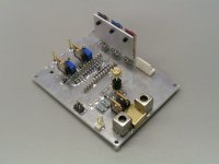
Latest MK6 has (charge compensated) 1uF 1210 size SMD film decoupling caps. Active divider decoupling caps are now 330nF 1206 size SMD film caps. Circuit is built on HF board and TDA1541A is mounted on an "open frame" socket in order to increase isolation resistance between the active divider decoupling pins.
I attached a photograph of this MK6.
For the digital section (SD-transport) I still use 1uF 1206 size X7R decoupling caps but I also plan to test 1uF film caps here.
1. You did use extreme LC-filtering for the oscillator, up to 20:th order or something, and now just a 40 ohm, resistor, quite a change, why !?
This filtering was an attempt to get rid of 78XX regulator large bandwidth noise. It didn't help much, once the interference is generated it is almost impossible to fully block it. So I tackled the problem by the source by using high resolution, large bandwidth, ultra low noise discrete voltage regulators.
2. This 40ohm, with 1uF will give approx. Fc of 4kHz. It is the same 5V feeding the 500ohm output resistor. Are you not modulating the oscillator with the analog output?
All bit currents (current flowing through passive I/V resistor, and unused bit currents) flow back into +5V. The MK6 has no active output stage, the output voltage is generated across a 500 Ohm I/V resistor. The power amp "measures" the ac voltage across this I/V resistor. This means that ripple voltage due to the audio signal is extremely low and no problem for the masterclock.
The RC filter offers sufficient attenuation of the 11.2896 MHz clock signal. The 40 Ohm Mobius Honeycomb wire wound resistor adds very little noise, so inter-modulating noise spectra are minimized.
The +5V power supply is taken out of the signal path as I use +5V (or a derived voltage) as reference. The TDA1541A keeps the output current through the passive I/V resistor constant (high PSRR). So we basically have a clean ac voltage across a 500R passive I/V resistor, even if the +5V power supply would be a bit noisy.
2. The flip-flops for WS, MCK, DATA are now feed by a 680ohm or 1.5k resistors from 5V, how does this work ?
I used these resistors in order to provide high series impedance over a very large bandwidth while keeping the circuit as simple as possible. Ferrite beads have problems with core saturation (DC current) and hysteresis.
The reclockers drive I2S attenuators, design is such that the reclocker only has to drive little over 12pF load. The signal amplitude equals 1.2Vpp instead of the usual 5Vpp. This not only reduces ground-bounce, it also reduces peak currents during signal transitions.
DATA and WS reclockers consume approx. 1.7mA each during normal operation (the reclockers run on approx. 2.4V power supply). Decoupling caps are not used here in order to minimize peak currents during signal transients. These can occur in combination with the TDA1541A I2S input circuit stray capacitance.
This greatly reduces crosstalk between BCK (that needs to remain as clean as possible) and WS / DATA signals.
The flip-flops remain stable under these conditions. Since the DATA and WS signals only need to be sampled during the positive going edge of BCK, fast transients are not required.
BCK is responsible for sample timing and needs to have fast transients. Because of the higher switching frequency and little over 12pF load, it consumes 3.8mA so 680 Ohm power supply series resistor is sufficient. Here a charge compensated 1uF SMD 1210 size film decoupling cap is used to supply required energy for fast transients. Charge compensation improves (film) cap small signal handling.
4. 1uF ceramics for decoupling everywhere, analog as well as digital?
(except the 47nF's for the TDA1541)
Latest MK6 has (charge compensated) 1uF 1210 size SMD film decoupling caps. Active divider decoupling caps are now 330nF 1206 size SMD film caps. Circuit is built on HF board and TDA1541A is mounted on an "open frame" socket in order to increase isolation resistance between the active divider decoupling pins.
I attached a photograph of this MK6.
For the digital section (SD-transport) I still use 1uF 1206 size X7R decoupling caps but I also plan to test 1uF film caps here.
Attachments
...............
The HDD "quality" doesn't matter at all here, since data is first buffered in RAM (Random Access Memory). When you play music trough a pc / mac, you are basically reading it from a semiconductor memory rather than a HDD. The HDD only fills the RAM buffer, it has plenty of time to do this. .............
Hello John,
Does playing CDs thru a PC has such benefit?
Hi John,
Thorough answer as always, but it generates more questions
There are 1uF in the schematics (C29, C30) or are you refering to something else? I get a sense that you are talking about yet another unpublished schematic of the Mk6 version?
My assumption was that you were 'balancing' the supply voltage for the flip-flops with the resistors, but it did not make sense with your published shematic. It has an error in the resistor values, the 680 ohm is on the WS but should be on BCK, ok fine, makes sense now.
Why do you never solder the TDA1541 chip directly to the board? Are you making too many changes all the time?
Keep on the good work John. It gets simpler and simpler and I like that.
//Per
Thorough answer as always, but it generates more questions
DATA and WS reclockers consume approx. 1.7mA each during normal operation (the reclockers run on approx. 2.4V power supply). Decoupling caps are not used here in order to minimize peak currents during signal transients.
There are 1uF in the schematics (C29, C30) or are you refering to something else? I get a sense that you are talking about yet another unpublished schematic of the Mk6 version?
BCK is responsible for sample timing and needs to have fast transients. Because of the higher switching frequency and little over 12pF load, it consumes 3.8mA so 680 Ohm power supply series resistor is sufficient.
My assumption was that you were 'balancing' the supply voltage for the flip-flops with the resistors, but it did not make sense with your published shematic. It has an error in the resistor values, the 680 ohm is on the WS but should be on BCK, ok fine, makes sense now.
What is "Charge compensation" ?Charge compensation improves (film) cap small signal handling.
Circuit is built on HF board and TDA1541A is mounted on an "open frame" socket in order to increase isolation resistance between the active divider decoupling pins.
Why do you never solder the TDA1541 chip directly to the board? Are you making too many changes all the time?
Keep on the good work John. It gets simpler and simpler and I like that.
//Per
Hi phi,
Yes I was talking about a MK6 that's assembled differently as a result of fine tuning.
Seems I didn't fix this error in the schematic, thanks for pointing this out.
Capacitors appear to have a charge "threshold". This means that applied charge on one capacitor plate has to exceed a certain threshold level before the other capacitor plate "follows". Compare it with a kind of mild cross-over distortion or electronic backlash. The audible effect is distortion and loss of resolution. Transformers offer better handling of low level signals, but have issues with higher signal amplitude.
The compensation consists of a carefully chosen bypass resistor that passes very small ac signal changes directly to the second plate.
Easy DAC chip swapping for testing different chips. Verifying correct circuit operation prior to installing the DAC chip. Easy trouble shooting (damaged DAC chip). Easy access to the parts that are mounted directly underneath the DAC chip such as decoupling caps. Cooling, the socket allows airflow underneath the chip and helps to keep chip temperature more constant. Varying chip temperature affects bit accuracy (passive dividers). Avoiding thermal stress that would occur during soldering. This thermal stress could affect chip (long term) accuracy and reliability.
The DAC evolved from a rather complicated design with 8 DAC chips and tube output stage to this simple straight-forward design. During development the main objective was best approximation of live sound quality.
Every part adds distortion because it isn't perfect. The fewer parts, the less distortion is added, and fewer flaws need fixing.
There are 1uF in the schematics (C29, C30) or are you refering to something else? I get a sense that you are talking about yet another unpublished schematic of the Mk6 version?
Yes I was talking about a MK6 that's assembled differently as a result of fine tuning.
It has an error in the resistor values, the 680 ohm is on the WS but should be on BCK, ok fine, makes sense now.
Seems I didn't fix this error in the schematic, thanks for pointing this out.
What is "Charge compensation" ?
Capacitors appear to have a charge "threshold". This means that applied charge on one capacitor plate has to exceed a certain threshold level before the other capacitor plate "follows". Compare it with a kind of mild cross-over distortion or electronic backlash. The audible effect is distortion and loss of resolution. Transformers offer better handling of low level signals, but have issues with higher signal amplitude.
The compensation consists of a carefully chosen bypass resistor that passes very small ac signal changes directly to the second plate.
Why do you never solder the TDA1541 chip directly to the board? Are you making too many changes all the time?
Easy DAC chip swapping for testing different chips. Verifying correct circuit operation prior to installing the DAC chip. Easy trouble shooting (damaged DAC chip). Easy access to the parts that are mounted directly underneath the DAC chip such as decoupling caps. Cooling, the socket allows airflow underneath the chip and helps to keep chip temperature more constant. Varying chip temperature affects bit accuracy (passive dividers). Avoiding thermal stress that would occur during soldering. This thermal stress could affect chip (long term) accuracy and reliability.
It gets simpler and simpler and I like that.
The DAC evolved from a rather complicated design with 8 DAC chips and tube output stage to this simple straight-forward design. During development the main objective was best approximation of live sound quality.
Every part adds distortion because it isn't perfect. The fewer parts, the less distortion is added, and fewer flaws need fixing.
A little progress - I was able to reclock BCK and the two DATA lines from the SAA7000. I had to connect BCK at pin 5, not 3, and feed reclockers with this signal and then DATA output to DACs again form pin 5. But, unfortunately, no way to get WS working!
One question about DEM reclock. With the TDA1540s even with 820pF caps disconnected I don't get distorted sound (?) like the 1541, so it's difficult to undestand if reclock is working or not. Bad thing. I connected two 12K resistors after each BAT17 diode in order to feed both TDA1540s, then a 2K2 resistor goes to -17V on each DEM pin. Is this theoretically correct?
Is it possible to get instrumental confirmation that DEM reclock is working?
Thank you.
Last edited:
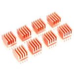
John, have you considered a more effective cooling of the DAC chip by using a heatsink on the top? I observed the TDA1541A gets rather hot during operation; cooling it surely has benefits... I use two copper heatsinks like on the picture, connected to the ground.Cooling, the socket allows airflow underneath the chip and helps to keep chip temperature more constant. Varying chip temperature affects bit accuracy (passive dividers). Avoiding thermal stress that would occur during soldering. This thermal stress could affect chip (long term) accuracy and reliability.
Attachments
- Home
- Source & Line
- Digital Line Level
- Building the ultimate NOS DAC using TDA1541A