Re: TDA1541A DEM clock frequency / decoupling cap value
I for one would be extremely interested on some scopecaptures of the waveforms on these pins with regard to capacitance values and DEM frequency.
-ecdesigns- said:The DA1541A modules with the new smaller heatsink can accomodate 0.68uF decoupling caps. This is possible by placing half of the caps on the component side, the other half on the solder side (there is plenty of room underneath the modules). The 1 uF for MSB could be increased to 2.2uF if desired.
That should be more than sufficient to get very low ripple current on all active divider outputs.
I for one would be extremely interested on some scopecaptures of the waveforms on these pins with regard to capacitance values and DEM frequency.
Hi maxlorenz,
Thanks for your reply [post #1599]
Yes making these vector drawings took a lot of time, but I wanted to make the assembly instructions as clear as possible. I still have to add detailed cable assembly drawings.
Yes, it's best to take your time for this project. In order to create some more space for the heatsinks of the stacked TDA1543 chips, you could mount both REF resistors and multilayer decoupling caps on the solder side.
Only 8 REF resistors will be used now, if you plan to use higher REF resistor values, use 22 K Ohm with 10uF decoupling cap.
When completed, I am very curious about the comparison between both the DI 16 you already built, and the one with the 8 x 3 configuration.
Thanks for your reply [post #1599]
I confess that I had not see before your excellent and very detailed assembly instructions at your "downloads" page. Wow.
Yes making these vector drawings took a lot of time, but I wanted to make the assembly instructions as clear as possible. I still have to add detailed cable assembly drawings.
I wait some R to begin with the DI8*4 project. This time I will take my time. Don't expect objectivity from my part with this one")
Yes, it's best to take your time for this project. In order to create some more space for the heatsinks of the stacked TDA1543 chips, you could mount both REF resistors and multilayer decoupling caps on the solder side.
Only 8 REF resistors will be used now, if you plan to use higher REF resistor values, use 22 K Ohm with 10uF decoupling cap.
When completed, I am very curious about the comparison between both the DI 16 you already built, and the one with the 8 x 3 configuration.
Hi Brent Welke,
Thanks for your reply [post # 1600]
The scope must be able to resolve phase deviations in the picosecond range, so a large bandwidth oscilloscope (40...100 MHz) is preferred.
Make sure you have a low jitter SMD 48 MHz oscillator module, check the datasheet.
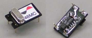
I now use a 48 MHz master clock oscillator based on a selected 16 MHz crystal and a WF10192. The 2.2 uF tantalium decoupling cap is soldered very close to the WF10192 power supply pins. The traces between crystal and the WF10192 are very short as well. There is a 2.7 K Ohm resistor in parallel with the crystal. The crystal oscillates on the third overtone.
The module only has a few parts and is quite easy to construct. I added a photograph of the module I experimented with, so soldering is very messy. The PCB is single sided.
Thanks for your reply [post # 1600]
The scope must be able to resolve phase deviations in the picosecond range, so a large bandwidth oscilloscope (40...100 MHz) is preferred.
Make sure you have a low jitter SMD 48 MHz oscillator module, check the datasheet.
I now use a 48 MHz master clock oscillator based on a selected 16 MHz crystal and a WF10192. The 2.2 uF tantalium decoupling cap is soldered very close to the WF10192 power supply pins. The traces between crystal and the WF10192 are very short as well. There is a 2.7 K Ohm resistor in parallel with the crystal. The crystal oscillates on the third overtone.
The module only has a few parts and is quite easy to construct. I added a photograph of the module I experimented with, so soldering is very messy. The PCB is single sided.
Attachments
DEM clock
I tried the DEM clock -ecdesigns- suggested (pin 16 of TDA1541A driven through a small capacitor, pin 17 connected to GND through 100 nF). Then searching the web I found the internal DEM circuit is most likely an emitter-coupled symmetrical multivibrator, and I modified the DEM drive circuit:
I divide my master clock of 4.2336 MHz by 6 with a 74HCT163 sync divider with 74LS00 feedback, this results in 705.6 kHz. This in turn is didided by 2 with a 74S74 D-flipflop. I couple both the inverting and non-inverting outputs to pin 16 and pin 17, respectively through 470 pF capacitors. The TTL-level squarewave is an overload at the DEM inputs, but no harm so far.
In the next step I will try 705.6 kHz (4.2336 MHz divided by 6, resulting in 16 DEM clock cycles per sample) or perhaps 529.2 kHz (4.2336 MHz divided by 8, resulting in 12 DEM clock cycles per sample). In the last version only 2 x 74S74 is necessary, and I can synchronize the DEM clock to the master clock by using the last flipflop that provides the opposite phase DEM clock signals.
Hi -ecdesigns-
Thanks for your tips.
That was my plan from the beginning. Plus vertical mounting of the PCB for better convective cooling...
Uf! I already bought 45K resistors for Rref. Too high?
Instead of multilayer I have Epcos polypropilene 100nF. I also have 10nf that I could parallel to them and see how it sounds...
As for the comparison, I am biased beforehand
I have enough chips to build two DI8*4 TDA1543 DACs
thanks to another beloved forum mate
Thanks for your tips.
In order to create some more space for the heatsinks of the stacked TDA1543 chips, you could mount both REF resistors and multilayer decoupling caps on the solder side.
That was my plan from the beginning. Plus vertical mounting of the PCB for better convective cooling...
Only 8 REF resistors will be used now, if you plan to use higher REF resistor values, use 22 K Ohm with 10uF decoupling cap.
Uf! I already bought 45K resistors for Rref. Too high?
Instead of multilayer I have Epcos polypropilene 100nF. I also have 10nf that I could parallel to them and see how it sounds...
As for the comparison, I am biased beforehand
I have enough chips to build two DI8*4 TDA1543 DACs
thanks to another beloved forum mate
maxlorenz said:
I have enough chips to build two DI8*4 TDA1543 DACs
thanks to another beloved forum mate
-ecdesigns- said:
The scope must be able to resolve phase deviations in the picosecond range, so a large bandwidth oscilloscope (40...100 MHz) is preferred.
I managed to check an buffered output of diy 27Mhz clock for jitter with a humble but here available 20 Mhz scope, the signal is finer visible on the screen, on cristal itself the signal is more blurry. I even managed to look 36mhz with this scope.
-ecdesigns- said:Hi oshifis,
I already tested 74H..74 chips, they had the worst jitter specs from all D flip-flops I tested, so I don't use them anymore. Using 2 D flip-flops in the same housing for different frequencies causes crosstalk and should be avoided. Unused INPUTS should always be connected to a steady signal level (GND). I got lowest jitter using D flip-flops from 74HC164 and 74F164 shift registers, that's why I use them a lot for timing critical circuits. The lower jitter is probably caused by the chip internal circuit architecture.
The 74xx161 is a synchronous divider. This means that the outputs change state fully synchronous with the input clock signal (BCK). The 74HC161 triggers on the positive going edge of BCK, this means that 74HC161 outputs also change on the positive going edge of BCK. The jitter at the divider outputs is very low (comparable to 74HC164), reclocking it with a 74..74 would actually increase jitter.
Hi EC,
How did you measure the jitter of the 74HC74 FF's? The jitter
induced by one of these, if correctly decoupled, should be very low.
Why do figure the shift register of same logic family - say HC, has
lower jitter?
cheers
Terry
Hi Terry Demol,
I measured jitter with a 60 MHz oscilloscope, I reclocked a 2.8224 MHz BCK signal using a 48 MHz master clock. Timing errors (jitter) show up as (random) displacements of signal transients in the time domain. When timing errors (jitter) is very low, al subsequent clock signal transients are perfectly aligned, resulting in a single visible transient.
The 74xx74 chip was part of a shiftregister reclocker with a 48 MHz master clock. Decoupling: 100uF electrolytic capacitor, and 100nF very close to the chip power supply. Unused inputs connected to GND/VCC. The HF path was kept as short as possible by using a power supply series resistor.
I already indicated this, it's probably caused by chip internal lay-out (location of traces / power supply routing to each separate MOSFET). MOSFETS draw peak currents during signal transients, causing short current surges. It's very likely that these peak currents affect circuit operation (phase shifts / crosstalk) depending on the chip lay-out.
How did you measure the jitter of the 74HC74 FF's? The jitter
induced by one of these, if correctly decoupled, should be very low.
I measured jitter with a 60 MHz oscilloscope, I reclocked a 2.8224 MHz BCK signal using a 48 MHz master clock. Timing errors (jitter) show up as (random) displacements of signal transients in the time domain. When timing errors (jitter) is very low, al subsequent clock signal transients are perfectly aligned, resulting in a single visible transient.
The 74xx74 chip was part of a shiftregister reclocker with a 48 MHz master clock. Decoupling: 100uF electrolytic capacitor, and 100nF very close to the chip power supply. Unused inputs connected to GND/VCC. The HF path was kept as short as possible by using a power supply series resistor.
Why do figure the shift register of same logic family - say HC, has
lower jitter?
I already indicated this, it's probably caused by chip internal lay-out (location of traces / power supply routing to each separate MOSFET). MOSFETS draw peak currents during signal transients, causing short current surges. It's very likely that these peak currents affect circuit operation (phase shifts / crosstalk) depending on the chip lay-out.
Jitter measurement
Hi tubee,
Yes you will be able to measure jitter on a 20 MHz scope, I assume you expanded the timebase with the x10 setting. So each scale division represents 1/200,000,000 = 5nS.
I am using a 60 MHz scope with x10 timebase setting, resulting in 1/600,000,000 = 2nS or 2000ps. Each sub-division (approx. 1mm) represents 2000 / 5 = 400ps. With a low intensity / good focus setting, you can easily subdivide this by 10 (0.1mm), similar to reading a Vernier calliper. This will allow for measuring jitter peak-to peak amplitudes down to 40ps (14ps rms) or better. Then there is the trace brightness, if all clock transients align perfectly, trace brightness appears higher then when they are slightly spread. So a brighter (signal transient) trace also indicates lower jitter amplitude.
20 MHz scope, 100ps (35ps rms)
40 MHz scope, 60ps (21ps rms)
60 MHz scope, 40ps (14ps rms)
100 MHz scope, 20ps (7ps rms)
Hi tubee,
I managed to check an buffered output of diy 27Mhz clock for jitter with a humble but here available 20 Mhz scope, the signal is finer visible on the screen, on cristal itself the signal is more blurry. I even managed to look 36mhz with this scope.
Yes you will be able to measure jitter on a 20 MHz scope, I assume you expanded the timebase with the x10 setting. So each scale division represents 1/200,000,000 = 5nS.
I am using a 60 MHz scope with x10 timebase setting, resulting in 1/600,000,000 = 2nS or 2000ps. Each sub-division (approx. 1mm) represents 2000 / 5 = 400ps. With a low intensity / good focus setting, you can easily subdivide this by 10 (0.1mm), similar to reading a Vernier calliper. This will allow for measuring jitter peak-to peak amplitudes down to 40ps (14ps rms) or better. Then there is the trace brightness, if all clock transients align perfectly, trace brightness appears higher then when they are slightly spread. So a brighter (signal transient) trace also indicates lower jitter amplitude.
20 MHz scope, 100ps (35ps rms)
40 MHz scope, 60ps (21ps rms)
60 MHz scope, 40ps (14ps rms)
100 MHz scope, 20ps (7ps rms)
The reclocker is wonderful
The reclocker is wonderful. I can't listen without it now.
I have been using this reclocker for a couple weeks now on a couple single TDA1543 chip USB DACs. I added a jumper so that I can switch between reclocker on/off while the music is playing.
This is my first experience with how jitter sounds. It took a couple weeks for me to fully appreciate and become accustom to the difference between the two settings. I didn't want to fall into the trap where a difference in sound seems to be a step forward when in time it becomes apparent it is not.
Reclocked the sound is much cleaner sounding and brings more life to the music. The music even sounds louder. How jitter sounds is well described here http://www.jitter.de/english/engc_navfr.html
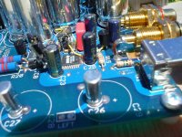
Included is a picture of how I implemented it. The clock beneath the stack of 4 SMD chips is the 48MHz clock with 1ps jitter. This used to be a 12MHz clock. I have at least a dozen DACs to modify. I will experiment with using two clocks (leaving the 12MHz clock alone) to see what affect that has. That would be a simpler mod then replacing the clock.
A few pages back I posted the Digikey parts list I used if anyone is interested in trying it on their DAC.
The reclocker makes a very welcome improvement to the sound. Now I cannot help but think is there even more improvement waiting to be had in reclocking.
I wish I had the test equipment to see exactly what is going on. However I can visualize the reclocker is not ideal. This is not news but I would like more discussion about it and so I go on about it...
The raw BCK and the master clock (48MHz) are not in sync and not exact multiples. The master clock is almost 17 times BCK's frequency. Reclocked BCK now falls on one of the 17 master clock transitions. The majority of the time 17 master clock cycles will pass between BCK pulses but as the clocks beat there will be times when the reclocker jumps to 16 or 18 clock cycles and then continues to be 17 until the next time they beat. This would add 1/48MHz jitter to that sample.
Since the raw BCK is jittery this event would likely affect a few BCK samples before proper reclocking is resumed.
Listening to the reclocker is proof that it spends the majority of its time providing low jitter clocking. At no time can I hear the moment(s) the reclocker is adding jitter. It either happens too often, too quickly, once an hour or something like that.
Perhaps someone with a quick mathematical mind can provide some numbers to the amount of jitter that occurs when the reclocker beats, how long it beats and the percentage of time reclocker is working correctly.
The reclocker is wonderful. I can't listen without it now.
I have been using this reclocker for a couple weeks now on a couple single TDA1543 chip USB DACs. I added a jumper so that I can switch between reclocker on/off while the music is playing.
This is my first experience with how jitter sounds. It took a couple weeks for me to fully appreciate and become accustom to the difference between the two settings. I didn't want to fall into the trap where a difference in sound seems to be a step forward when in time it becomes apparent it is not.
Reclocked the sound is much cleaner sounding and brings more life to the music. The music even sounds louder. How jitter sounds is well described here http://www.jitter.de/english/engc_navfr.html
Included is a picture of how I implemented it. The clock beneath the stack of 4 SMD chips is the 48MHz clock with 1ps jitter. This used to be a 12MHz clock. I have at least a dozen DACs to modify. I will experiment with using two clocks (leaving the 12MHz clock alone) to see what affect that has. That would be a simpler mod then replacing the clock.
A few pages back I posted the Digikey parts list I used if anyone is interested in trying it on their DAC.
The reclocker makes a very welcome improvement to the sound. Now I cannot help but think is there even more improvement waiting to be had in reclocking.
I wish I had the test equipment to see exactly what is going on. However I can visualize the reclocker is not ideal. This is not news but I would like more discussion about it and so I go on about it...
The raw BCK and the master clock (48MHz) are not in sync and not exact multiples. The master clock is almost 17 times BCK's frequency. Reclocked BCK now falls on one of the 17 master clock transitions. The majority of the time 17 master clock cycles will pass between BCK pulses but as the clocks beat there will be times when the reclocker jumps to 16 or 18 clock cycles and then continues to be 17 until the next time they beat. This would add 1/48MHz jitter to that sample.
Since the raw BCK is jittery this event would likely affect a few BCK samples before proper reclocking is resumed.
Listening to the reclocker is proof that it spends the majority of its time providing low jitter clocking. At no time can I hear the moment(s) the reclocker is adding jitter. It either happens too often, too quickly, once an hour or something like that.
Perhaps someone with a quick mathematical mind can provide some numbers to the amount of jitter that occurs when the reclocker beats, how long it beats and the percentage of time reclocker is working correctly.
Attachments
-ecdesigns- said:Hi Terry Demol,
I measured jitter with a 60 MHz oscilloscope, I reclocked a 2.8224 MHz BCK signal using a 48 MHz master clock. Timing errors (jitter) show up as (random) displacements of signal transients in the time domain. When timing errors (jitter) is very low, al subsequent clock signal transients are perfectly aligned, resulting in a single visible transient.
The 74xx74 chip was part of a shiftregister reclocker with a 48 MHz master clock. Decoupling: 100uF electrolytic capacitor, and 100nF very close to the chip power supply. Unused inputs connected to GND/VCC. The HF path was kept as short as possible by using a power supply series resistor.
Hi EC,
2.8224MHz and 48MHz arent syncronous or integer multiples
so I don't quite understand how this can work properly.
I would imagine you will be generating sidebands and
running into DFF setup / timing issues.
Maybe this is the 'jitter' that you are seeing?
cheers
Terry
My (almost completed) DI16
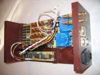
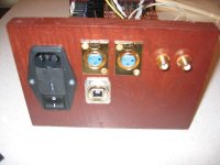
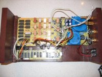
Attached are some pictures of my almost completed DI-16.
I used a left over piece of oak I had to make the case, and plan to fold some perforated stainless steel over the top as a cover that will provide ventilation.
I haven't hooked up the balanced outputs yet.
I also need to hook up a small USB cable to the pass through USB connector before I can close it up.
My (almost completed) DI16
Attached are some pictures of my almost completed DI-16.
I used a left over piece of oak I had to make the case, and plan to fold some perforated stainless steel over the top as a cover that will provide ventilation.
I haven't hooked up the balanced outputs yet.
I also need to hook up a small USB cable to the pass through USB connector before I can close it up.
Attachments
Jitter / ripple
Hi Terry Demol,
I ran tests with both 48 and 47.9808 MHz, the oscilloscope shows very little difference between the BCK signal reclocked by either 48 or 47.9808 MHz.
The sound quality (sound depth, transparency, details, midrange and bass) I am getting with the DI 8M after the latest mods (Vishay bulk metal foil I/V resistors and 3.3mA bias current for the LM4562), show that jitter isn't causing any audible problems whatsoever.
More disturbing is the fact that sample amplitude ripple during the time the sample is output, causes similar problems as jitter. If you managed to get jitter values very low, you're only halfway.
The TDA1541A is one of the very few chips that have decoupling caps on the active current divider outputs. This enables the possibility to achieve a very low ripple signal on the current output. By increasing both DEM clock rate and decoupling capacitor values, the ripple voltage on the output can be reduced to very low levels.
I think that the jitter frequency components (the way the clock signal phase is modulated) have the biggest impact. If we take a perfect clock signal (square-wave) with zero jitter, all subsequent signal transients are perfectly time-aligned. When viewed on the oscilloscope, we should see a clear square-wave signal with very clean signal transients.
So I would say that it's most important to have as many clock signal transients time-aligned as possible. When a clock signal is phase modulated with noise, almost all signal transients take place with slightly different time intervals, and are by no means time-aligned. The clock signal shows hazy transients on the oscilloscope, the exact clock signal transients can no longer be determined.
With asynchronous reclocking, using two cascaded D-flip flops, we get two time displaced clock signal transients, both have the same brightness when viewed on the oscilloscope. So approx. 50% of the transients are time aligned in one "cluster" the other 50% in the second "cluster". Since the transients within a cluster are still perfectly aligned, both clock signal transients can still be determined accurately. Despite of the much higher time displacement, this clock signal will actually produce a sound quality that doesn't suggest high jitter is present.
The shiftregister reclocker is basically a digital one-shot circuit that generates a well defined pulse after each positive going edge of BCK. The pulsewidth is always exactly 7 masterclock pulses wide (BCK input = 2.8224 MHz / masterclock = 48 MHz). In order to maintain sync with the BCK input signal, the time between two subsequent fixed pulses may vary, but since both BCK and the masterclock are almost perfect multiples, there are few corrections needed. The shiftregister reclocker is also able to phase-lock to the BCK input signal, within the available time resolution.
The BCK output of the shiftregister reclocker looks like a single square-wave on the oscilloscope (unlike an asynchronous reclocked BCK signal). When the brightness is turned-up, a very dim second clock signal transient becomes visible, this is caused by the sporadic corrections needed to maintain perfect sync.
Hi Terry Demol,
2.8224MHz and 48MHz arent syncronous or integer multiples
so I don't quite understand how this can work properly.
I would imagine you will be generating sidebands and
running into DFF setup / timing issues.
I ran tests with both 48 and 47.9808 MHz, the oscilloscope shows very little difference between the BCK signal reclocked by either 48 or 47.9808 MHz.
The sound quality (sound depth, transparency, details, midrange and bass) I am getting with the DI 8M after the latest mods (Vishay bulk metal foil I/V resistors and 3.3mA bias current for the LM4562), show that jitter isn't causing any audible problems whatsoever.
More disturbing is the fact that sample amplitude ripple during the time the sample is output, causes similar problems as jitter. If you managed to get jitter values very low, you're only halfway.
The TDA1541A is one of the very few chips that have decoupling caps on the active current divider outputs. This enables the possibility to achieve a very low ripple signal on the current output. By increasing both DEM clock rate and decoupling capacitor values, the ripple voltage on the output can be reduced to very low levels.
I think that the jitter frequency components (the way the clock signal phase is modulated) have the biggest impact. If we take a perfect clock signal (square-wave) with zero jitter, all subsequent signal transients are perfectly time-aligned. When viewed on the oscilloscope, we should see a clear square-wave signal with very clean signal transients.
So I would say that it's most important to have as many clock signal transients time-aligned as possible. When a clock signal is phase modulated with noise, almost all signal transients take place with slightly different time intervals, and are by no means time-aligned. The clock signal shows hazy transients on the oscilloscope, the exact clock signal transients can no longer be determined.
With asynchronous reclocking, using two cascaded D-flip flops, we get two time displaced clock signal transients, both have the same brightness when viewed on the oscilloscope. So approx. 50% of the transients are time aligned in one "cluster" the other 50% in the second "cluster". Since the transients within a cluster are still perfectly aligned, both clock signal transients can still be determined accurately. Despite of the much higher time displacement, this clock signal will actually produce a sound quality that doesn't suggest high jitter is present.
The shiftregister reclocker is basically a digital one-shot circuit that generates a well defined pulse after each positive going edge of BCK. The pulsewidth is always exactly 7 masterclock pulses wide (BCK input = 2.8224 MHz / masterclock = 48 MHz). In order to maintain sync with the BCK input signal, the time between two subsequent fixed pulses may vary, but since both BCK and the masterclock are almost perfect multiples, there are few corrections needed. The shiftregister reclocker is also able to phase-lock to the BCK input signal, within the available time resolution.
The BCK output of the shiftregister reclocker looks like a single square-wave on the oscilloscope (unlike an asynchronous reclocked BCK signal). When the brightness is turned-up, a very dim second clock signal transient becomes visible, this is caused by the sporadic corrections needed to maintain perfect sync.
Hi -ecdesigns-,
The built of my new 8*4TDA1543 DAC is at standby because of 100nf caps out of stock
My computer expert advisor installed me OSX (MAC) on my PC instead of Ubuntu because he lacked experience on the later. Sound improvement is significant compared to XP.
What software do you recommend to listen and rip music? (lossless format)
Thanks,
M
- Home
- Source & Line
- Digital Line Level
- Building the ultimate NOS DAC using TDA1541A