maxlorenz said:Believe me, i do know what you mean!
I have Ubuntu already but have only played around with it. I can't access internet throught it yet. When I 'll do I'll make it my main OS, no problem.
Do you have a network card on this pc?
Btw tried to get a pcm2706/7, ti wiped me from the list
(samples)BInary twos complement
Hello ECdesigns,
If I understood your posts, You use a differential output stage. The differential signal is build by two groups of DACs. One group is fed with inverted data.
A negative number for the DAC is represented in twos complement. This is the difference to the number system base -1. In case of the binary system the difference to base is the inversion. The term -1 is missed. So in the DAC group fed with the inverted data there is a error with the value of 1. In the combined result after the differential output stage the error is halved to the value of 0.5.
This error is extremely small, but speaking of the ultimate DAC perhaps is the subtraction worth the effort.
The second solution would be to left out the differential mode. Capacitor coupling handles new distortion, so the error of value of 0.5 is perhaps the better way. Instead of capacitor coupling, there could be used a transformer. I made a good experience this way. But it is the more costly solution. Good transformers are rare, but they bring for me a live quality to the music. Price should not be an issue in an ultimate device.
Ciao
Peter
Hi dddac,
Thanks for your reply [post #1492]
My aim is "live" sound quality, not elevate kits. The differences I mention are based on both measurements and listening tests. I shared a lot of information and research results on this thread for almost a year now, that document the design / optimation process step by step. By carefully studying this information, it must become clear why certain improvements resulted in better performance and why.
Paper studies are fine, but sometimes it requires an entirely different approach in order to get real improvements.
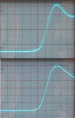
I am not going to explain why I think USBDI2S has better performance, I just added oscillograms of BCK using the standard TI PCM2706 application (upper oscillogram), and the same BCK signal after the shiftregister reclocker (lower oscillogram). Then consider that I continued to optimize the USBDI2S interface, after these pictures were taken.
It was not my intention cracking your designs, and if it appeared as such, I apoligize for this. You make great audio kits, and this is confirmed by the feedback of many people who built them. I have respect for people who design products like these.
I use the term "huge" in a relative sense. Small improvements can result in a very clearly improvement in sound quality, I might call this huge in order to express the significance of this improvement in comparison with other (previous) improvements. I sometimes get too enthusiastic, like with the transistor radio incident, it was just a way to express how I perceived the audible improvement at that time.
Jitter consists of specific frequency components, and these frequency components together have a certain average amplitude. The more different frequencies present, the worse it gets, so it's not just the jitter amplitude degrading sound quality, it's also the contained frequency components.
Jitter is only one of the many factors that degrade sound quality, and the sum of all these factors determine how an audio set sounds. One factor could attenuate or increase another. You can't pick-out one single component, without tuning it to the rest of the audio set. Basically optimizing a DAC, includes optimizing the interface that drives it, and all that's connected to the DAC, interlinks, amplifiers, and speakers. This is why I suggested trying to use the USBDI2S module, as it forms a unity with the DI DACs.
That sounds like a good solution, thanks. I appreciate your expertise on paralleling TDA1543 chips
It's not for me to decide who's designs are worthy or not. I leave that up to the people who build, test, and compare these designs.
Thanks for your reply [post #1492]
I hope your comments on "huge" differences are based on comparing the two designs life and not based on trying to elevate your kits compared to my humble design based on paper study ?
My aim is "live" sound quality, not elevate kits. The differences I mention are based on both measurements and listening tests. I shared a lot of information and research results on this thread for almost a year now, that document the design / optimation process step by step. By carefully studying this information, it must become clear why certain improvements resulted in better performance and why.
Paper studies are fine, but sometimes it requires an entirely different approach in order to get real improvements.
I am not going to explain why I think USBDI2S has better performance, I just added oscillograms of BCK using the standard TI PCM2706 application (upper oscillogram), and the same BCK signal after the shiftregister reclocker (lower oscillogram). Then consider that I continued to optimize the USBDI2S interface, after these pictures were taken.
I would like to call for some more prudence on cracking my designs on expected audible outcome. You would be adding yourself to a line of people who judge the dddac on paper and drawing conclusions on expected measurements they never did, not to mention, never listened to it. Which is strange, as I very much like your approach of combining pure technic with intense listening sessions.
It was not my intention cracking your designs, and if it appeared as such, I apoligize for this. You make great audio kits, and this is confirmed by the feedback of many people who built them. I have respect for people who design products like these.
May be your comment on "huge" is just the way you express yourself.... I remember you talking about your earlier design sounded like a "transistor radio", which was hard to believe too
I use the term "huge" in a relative sense. Small improvements can result in a very clearly improvement in sound quality, I might call this huge in order to express the significance of this improvement in comparison with other (previous) improvements. I sometimes get too enthusiastic, like with the transistor radio incident, it was just a way to express how I perceived the audible improvement at that time.
If the USB module would be that bad and jittery as you suggest and as you conclude therefore must be effecting negatively the sound, it would not be so much better compared to the best SPDIF like implementations, I have heard my self (and many others)
Jitter consists of specific frequency components, and these frequency components together have a certain average amplitude. The more different frequencies present, the worse it gets, so it's not just the jitter amplitude degrading sound quality, it's also the contained frequency components.
Jitter is only one of the many factors that degrade sound quality, and the sum of all these factors determine how an audio set sounds. One factor could attenuate or increase another. You can't pick-out one single component, without tuning it to the rest of the audio set. Basically optimizing a DAC, includes optimizing the interface that drives it, and all that's connected to the DAC, interlinks, amplifiers, and speakers. This is why I suggested trying to use the USBDI2S module, as it forms a unity with the DI DACs.
A solution to the buffer problem could be to use buffering at the input of the towers, as I do to enable larger quantities of towers to be used in parallel. In that case a 8 x 12 1543 implementation would be no problem for Max
That sounds like a good solution, thanks. I appreciate your expertise on paralleling TDA1543 chips
keep up the good work, you do great stuff and I read your posts with more than average interest, but don't try to act as if your designs are worthy and others are absoluely not. That would do no justice and I consider this as unfair.
It's not for me to decide who's designs are worthy or not. I leave that up to the people who build, test, and compare these designs.
Attachments
Hi horus,
Thanks for your reply
The kit product configurator on my website lets you generate a pdf file online, containing all information about the selected project.
About sound comparison with commercial DACs, perhaps there will be some valuable feedback after demonstrations at audio shows and High-End audio clubs, that are planned this year.
Thanks for your reply
-ecdesigns- , how much does a project like this cost?
Where would you place it in comparison with commercial DACs ?(sound comparison)
The kit product configurator on my website lets you generate a pdf file online, containing all information about the selected project.
About sound comparison with commercial DACs, perhaps there will be some valuable feedback after demonstrations at audio shows and High-End audio clubs, that are planned this year.
-ecdesigns- said:... Then consider that I continued to optimize the USBDI2S interface, after these pictures were taken.
Do you plan to publish modifications to your USB/I2S interface that you made after this circuit was published in post #1024?
I built Doede's USB/I2S reciver and results are remarkable, and as I have some spare PCM2707's I would like to build your version too, to make a comparison. I see your implemetation of PCM2707 is quite different from many circuits that can be found, so it's wery intriguing to try that solution.
I use Pedja's AYA DAC, very good TDA1541 NOS DAC.
I must admit that your work is quite remarkable!
Regards,
Zoran
OT nº1:
Omainik: try your CDPRO with some mechanical (non-magnetic) clamp system for the CD, like a little wraped paper or else...
OT nº2:
Tubee:
I believe I don't, but today an expert will come by...
Me too Digikey US$6.8
http://www.digikey.com/scripts/DkSearch/dksus.dll?Detail?Ref=61918&Row=102060&Site=US
DDDAC,
So, one extra buffer for each tower, wich could allow for n chips/tower
Wich device? 74VHC125?
Thanks,
M
Omainik: try your CDPRO with some mechanical (non-magnetic) clamp system for the CD, like a little wraped paper or else...
OT nº2:
Tubee:
Do you have a network card on this pc?
I believe I don't, but today an expert will come by...
Btw tried to get a pcm2706/7, ti wiped me from the list (samples)
Me too
Digikey US$6.8http://www.digikey.com/scripts/DkSearch/dksus.dll?Detail?Ref=61918&Row=102060&Site=US
DDDAC,
A solution to the buffer problem could be to use buffering at the input of the towers, as I do to enable larger quantities of towers to be used in parallel. In that case a 8 x 12 1543 implementation would be no problem for Max
So, one extra buffer for each tower, wich could allow for n chips/tower
Wich device? 74VHC125?
Thanks,
M
maxlorenz said:
DDDAC,
So, one extra buffer for each tower, wich could allow for n chips/tower
Wich device? 74VHC125?
Thanks,
M
Or 74HC125, as the VHC is obsolete and very hard to get ....
Each of those drives easily 12 1543's. probably more, but there are limits of course....
doede
maxlorenz said:The general picture,

M
M: Nice special transformer you used (the black&white one) where did you get it from?
Hi horus,
Ok, this could cause troubles,
All comparisons and remarks below are my personal opinion.
I have listened to many commercial DACs, I have to add that these DACs were obviously connected to different audio sets (CD transports, amplifiers, speakers and interlinks). You don't listen to the DAC only, but at the sum off all audio components, including the DAC.
I visited the VAD audio show in Veldhoven, there was also a band performing live, so a direct comparison between that live performance and the audio sets could be made. When listening to the many commercial audio sets, I never got the impression of listening to a live performance. What I missed was the spatial information, that's always present when listening to a live performance, instead the sound was "flat".
The DI 8M with the new 352.8 KHz DEM clock, and the sonic resonators, will produce a perceived sound quality that very closely matches that of a live performance. In other words it' able to provide the spatial information left in the CD recording. This also depends on the recording itself of course.
If the recording is made in a studio, and the lead singer is recorded in a separate box with phone booth acoustics, while the background singers are recorded in a larger room. Most commercial DACs will produce a rather flat sound with little information about acoustic space, sound "seems" ok. The DI DACs will produce the sound of the background singers with the acoustics of a large room, the lead singer is "separated" from it, and will have phone booth acoustics. The lead singer is no longer "integrated in" the sound. You clearly notice it doesn't sound "natural".
When listening to recordings that are made in a single room / space, the recorded sounds forms a unity, as the acoustic information is now correct, both lead singer and background singers now share the same space and produce sound reflections within that same space. These reflected sounds carry the information about acoustic space, it tells if the recording is made in a small room, a concert hall or outside in the open. It's this information that adds "live" characteristics to sound.
The DI DACs fully preserve this information about acoustic space (that translates to extremely low sample-to sample fluctuations). This is possible because a DI DAC doesn't average / integrate between many samples, like OS DACs do, so even the slightest sample-to sample fluctuations are accurately reproduced.
The absence of an analog filter even increases the DI DACs ability to provide very accurate information about acoustic space. Because DI DACs don't use oversampling, the extra harmonics usually produced as a result of oversampling doesn't need to be filtered out with a brickwall filter. Still the DI DACs have comparable or higher (time) resolution than OS DACs.
Information about acoustic space is very sensitive to ripple voltages on the generated samples, the slightest noise, hum, harmonics on the samples will blur the information about acoustic space, that's why a clean power supply and fast settling times are so important. I solved this problem by using a balanced design.
Jitter has a similar effect, it modulates the sample frequency with frequency components, causing incorrect sample timing.
Finally I removed all non-linear components from the signal path, these could change phase of specific frequencies and distort the spatial information (sound coloring), so I solved this by using a fully DC coupled design.
DI DACs are basically NOS DACs, and are less sensitive to jitter, but I still try to get jitter as low as possible. This is absolutely necessary to fully preserve information about acoustic space.
The difference between a good NOS DAC and the DI DAC, is that a DI DAC produces a much more refined and accurate sound image, the top end is crystal clear and smooth (no edge), the sound is loaded with micro information. This is usually not the case with most NOS DACs, because they need some kind of analog filtering to remove most of the "sharp edges". This also removes some micro-information in the process. Without any filtering, NOS DACs produce a course output signal that isn't optimal either.
But as a personal opinion where would you place your DAC among commercial ones?
Ok, this could cause troubles,
All comparisons and remarks below are my personal opinion.
I have listened to many commercial DACs, I have to add that these DACs were obviously connected to different audio sets (CD transports, amplifiers, speakers and interlinks). You don't listen to the DAC only, but at the sum off all audio components, including the DAC.
I visited the VAD audio show in Veldhoven, there was also a band performing live, so a direct comparison between that live performance and the audio sets could be made. When listening to the many commercial audio sets, I never got the impression of listening to a live performance. What I missed was the spatial information, that's always present when listening to a live performance, instead the sound was "flat".
The DI 8M with the new 352.8 KHz DEM clock, and the sonic resonators, will produce a perceived sound quality that very closely matches that of a live performance. In other words it' able to provide the spatial information left in the CD recording. This also depends on the recording itself of course.
If the recording is made in a studio, and the lead singer is recorded in a separate box with phone booth acoustics, while the background singers are recorded in a larger room. Most commercial DACs will produce a rather flat sound with little information about acoustic space, sound "seems" ok. The DI DACs will produce the sound of the background singers with the acoustics of a large room, the lead singer is "separated" from it, and will have phone booth acoustics. The lead singer is no longer "integrated in" the sound. You clearly notice it doesn't sound "natural".
When listening to recordings that are made in a single room / space, the recorded sounds forms a unity, as the acoustic information is now correct, both lead singer and background singers now share the same space and produce sound reflections within that same space. These reflected sounds carry the information about acoustic space, it tells if the recording is made in a small room, a concert hall or outside in the open. It's this information that adds "live" characteristics to sound.
The DI DACs fully preserve this information about acoustic space (that translates to extremely low sample-to sample fluctuations). This is possible because a DI DAC doesn't average / integrate between many samples, like OS DACs do, so even the slightest sample-to sample fluctuations are accurately reproduced.
The absence of an analog filter even increases the DI DACs ability to provide very accurate information about acoustic space. Because DI DACs don't use oversampling, the extra harmonics usually produced as a result of oversampling doesn't need to be filtered out with a brickwall filter. Still the DI DACs have comparable or higher (time) resolution than OS DACs.
Information about acoustic space is very sensitive to ripple voltages on the generated samples, the slightest noise, hum, harmonics on the samples will blur the information about acoustic space, that's why a clean power supply and fast settling times are so important. I solved this problem by using a balanced design.
Jitter has a similar effect, it modulates the sample frequency with frequency components, causing incorrect sample timing.
Finally I removed all non-linear components from the signal path, these could change phase of specific frequencies and distort the spatial information (sound coloring), so I solved this by using a fully DC coupled design.
DI DACs are basically NOS DACs, and are less sensitive to jitter, but I still try to get jitter as low as possible. This is absolutely necessary to fully preserve information about acoustic space.
The difference between a good NOS DAC and the DI DAC, is that a DI DAC produces a much more refined and accurate sound image, the top end is crystal clear and smooth (no edge), the sound is loaded with micro information. This is usually not the case with most NOS DACs, because they need some kind of analog filtering to remove most of the "sharp edges". This also removes some micro-information in the process. Without any filtering, NOS DACs produce a course output signal that isn't optimal either.
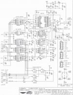
USBDI2S schematics
Hi ZII Pcelar,
Thanks for your reply,
The schematic in post #1024 is only an early prototype, the new USBDI2S module is much more refined, it has extensive power supply decoupling down to chip level. There is an autodetecting input source selection, and the decoupling capacitor values are changed. It has split power supplies and an on-board DI2S transceiver between USB interface and I2S output.
The tweaked version in the DI 8M has even more extensive power supply decoupling, a 330uF tantalium capacitor for master clock decoupling. I also applied some trace capacity compensations. It also has a discrete low jitter master clock oscillator module.
The PCB traces are fully gold plated, this also improves HF performance. I had to re-design the PCB many times before I got optimal HF performance and minimal crosstalk / lowest jitter, it's all quite critical.
I added the schematic diagram that comes with the kits.
Hi ZII Pcelar,
Thanks for your reply,
Do you plan to publish modifications to your USB/I2S interface that you made after this circuit was published in post #1024?
I built Doede's USB/I2S reciver and results are remarkable, and as I have some spare PCM2707's I would like to build your version too, to make a comparison. I see your implemetation of PCM2707 is quite different from many circuits that can be found, so it's wery intriguing to try that solution.
I use Pedja's AYA DAC, very good TDA1541 NOS DAC.
The schematic in post #1024 is only an early prototype, the new USBDI2S module is much more refined, it has extensive power supply decoupling down to chip level. There is an autodetecting input source selection, and the decoupling capacitor values are changed. It has split power supplies and an on-board DI2S transceiver between USB interface and I2S output.
The tweaked version in the DI 8M has even more extensive power supply decoupling, a 330uF tantalium capacitor for master clock decoupling. I also applied some trace capacity compensations. It also has a discrete low jitter master clock oscillator module.
The PCB traces are fully gold plated, this also improves HF performance. I had to re-design the PCB many times before I got optimal HF performance and minimal crosstalk / lowest jitter, it's all quite critical.
I added the schematic diagram that comes with the kits.
Attachments
-ecdesigns- said:Hi horus,
Ok, this could cause troubles,
The difference between a good NOS DAC and the DI DAC, is that a DI DAC produces a much more refined and accurate sound image, the top end is crystal clear and smooth (no edge), the sound is loaded with micro information.
This is usually not the case with most NOS DACs, because they need some kind of analog filtering to remove most of the "sharp edges". This also removes some micro-information in the process. Without any filtering, NOS DACs produce a course output signal that isn't optimal either.

Dear John,
Well, I believe, this is a point for some contemplation / discussion... If you state that micro information get lost by filtering, how come, that my 300B SE end amplifiers, which filters the signal, as the rest of the audio chain does, deliver MUCH more micro detail and texture than "simple" tube amplifiers or Transistor amplifiers ?? There most be much more on the micro detail thing than only the filtering.
My experience is, that paralelling chips and reclocking (even a-synchrone) for example delivers a gain in micro detail, regardles of the filtering directly after the dac. In fact the whole audiochain behind the audio dac is a kind of low pass filter. Indeed the sharp edges could cause problems here, but only if negative feedback is used imo. In a non FB chain (like most SE tube amplifier chains, which I happen to use) I hear no negative effects. May be that is why NOS dacs normally score exceptionally good in chains where non-FB Tube amplifiers are used ? (does not mean that they sound bad in others of course)
I do strongly believe, that the interpolation you are doing does improve the smoothness of the sound and I hope to get some time to use one of your timing chains to drive my dddac towers. That could be a great combination
best regards
doede
Hi omalnlk
Thanks for your reply [post #1500],
If you can get hold of 8 pcs TDA1541A, and you really want the best, the following might be interesting:
Last week Onnosr called me, he was very enthusiastic about DEM clock modifications he had made.
This made me curious, and I started experimenting with the DI 8M DEM clock circuit....again.
Very strange things happened with 352.8 KHz DEM clock and the DEM clock injection circuit I was using.
I put a selector switch on the DI 8M to toggle between 176.4 KHz and 352.8 KHz, checked for correct operation and connected it to the set in my living room. The DI 8M was already performing at a very high level, and I had my doubts if it could be further improved this way.
I switched-on, let it warm-up for half an hour, and listened to the 176.4 KHz switch position, sound quality was still the same as I was used to. Then I toggled the switch to 352.8 KHz, suddenly all voices and instruments locked into position with pinpoint precision. I was hearing instruments left, right, in front and behind me. This was a major impact on sound quality.
The TDA1541A DEM clock circuit is the key to reveal it's hidden performance, all it takes is using an external 352.8 KHz clock that runs synchronous with BCK and a simple DEM clock injection circuit.
Onnosr kindly send me original schematics of the TDA1541A internal circuitry and a detailed theory of operation. I want to thank Onnosr very much for this. Now I can get started...
I already studied the current output circuit, and in particular the bit switches. This confirmed my choice of keeping ac voltage at the DAC output as low as possible. The slightest ac components on the TDA1541A output prevent correct operation of these bit switches, resulting in fluctuating bit errors / settling time problems. You preferably want to keep the ac voltage at the DAC current output at zero. In other words the 25mV compliance is an "absolute maximum" value. Especially at these very high performance levels, these details do become ever so important.
So using an Op-amp I/V with a high-performance Op-amp wasn't such a bad idea after all, now the ac voltage at the DAC current outputs is very close to zero. This ensures (measurable) lower settling times. Based on the documentation I received from Onnosr, there is also an indication that paralleling multiple TDA1541A / TDA1543 DAC chips could improve settling time.
TDA1541A / TDA1543 use low-voltage swing unsaturated current mode logic (CML) that ensures high speed and low interference noise. Transistors are used instead of MOSFETs, that explains the relatively high power consumption / heat dissipation. All digital inputs have constant current source pull ups, so the driver circuit needs to supply most current at logic "0" (400uA), and lowest current at logic "1" (20uA). There is also no need to use high drive voltages (5V) since the trigger treshold is quite low, around 1.4V (LOW = 0.8V, HIGH=2V). The inputs are TTL compatible.
You can use a standard 48 MHz crystal module, Onnosr used this type of crystal module as well. as far as I know there are no difficult to get parts.
Thanks for your reply [post #1500],
yesterday I compared for a long time my tda1541 design to the tda1543 version, so I can make a decision which of your boards DI-8 / DI-16 is the better solution for me to try direct interpolation. I have 8 x TDA1541a left and so 60 pieces of the tda1543. The 1541 was always better.
With a power consumption of 50-60 mA the small IC of the tda1543 gets pretty warm in spite of massive cooling. So I put the DACs under oil. With the better cooling the TDA1543 version was under 30°C and achieved the same quality level as the tda1541. On most tracks the difference is inaudible. On some tracks it is a matter of taste but not a quality difference. tda1541 is more transparent and clear, tda1543 seems to have more powerful dynamics.
So I currently tend to the DI-16 version.
If you can get hold of 8 pcs TDA1541A, and you really want the best, the following might be interesting:
Last week Onnosr called me, he was very enthusiastic about DEM clock modifications he had made.
This made me curious, and I started experimenting with the DI 8M DEM clock circuit....again.
Very strange things happened with 352.8 KHz DEM clock and the DEM clock injection circuit I was using.
I put a selector switch on the DI 8M to toggle between 176.4 KHz and 352.8 KHz, checked for correct operation and connected it to the set in my living room. The DI 8M was already performing at a very high level, and I had my doubts if it could be further improved this way.
I switched-on, let it warm-up for half an hour, and listened to the 176.4 KHz switch position, sound quality was still the same as I was used to. Then I toggled the switch to 352.8 KHz, suddenly all voices and instruments locked into position with pinpoint precision. I was hearing instruments left, right, in front and behind me. This was a major impact on sound quality.
The TDA1541A DEM clock circuit is the key to reveal it's hidden performance, all it takes is using an external 352.8 KHz clock that runs synchronous with BCK and a simple DEM clock injection circuit.
In Your design the I/V conversion is always done with a opamp. The tube stage is connected after that first opa. I want to try this first I/V conversion stage with a tube transconductance amplifier.
Onnosr kindly send me original schematics of the TDA1541A internal circuitry and a detailed theory of operation. I want to thank Onnosr very much for this. Now I can get started...
I already studied the current output circuit, and in particular the bit switches. This confirmed my choice of keeping ac voltage at the DAC output as low as possible. The slightest ac components on the TDA1541A output prevent correct operation of these bit switches, resulting in fluctuating bit errors / settling time problems. You preferably want to keep the ac voltage at the DAC current output at zero. In other words the 25mV compliance is an "absolute maximum" value. Especially at these very high performance levels, these details do become ever so important.
So using an Op-amp I/V with a high-performance Op-amp wasn't such a bad idea after all, now the ac voltage at the DAC current outputs is very close to zero. This ensures (measurable) lower settling times. Based on the documentation I received from Onnosr, there is also an indication that paralleling multiple TDA1541A / TDA1543 DAC chips could improve settling time.
TDA1541A / TDA1543 use low-voltage swing unsaturated current mode logic (CML) that ensures high speed and low interference noise. Transistors are used instead of MOSFETs, that explains the relatively high power consumption / heat dissipation. All digital inputs have constant current source pull ups, so the driver circuit needs to supply most current at logic "0" (400uA), and lowest current at logic "1" (20uA). There is also no need to use high drive voltages (5V) since the trigger treshold is quite low, around 1.4V (LOW = 0.8V, HIGH=2V). The inputs are TTL compatible.
Is it difficult to obtain a low jitter crystal for the USB receiver board? Do You have a source? Are there other difficult to get parts?
You can use a standard 48 MHz crystal module, Onnosr used this type of crystal module as well. as far as I know there are no difficult to get parts.
Hi omalnlk
Thanks for your reply [post #1500],
If you can get hold of 8 pcs TDA1541A, and you really want the best, the following might be interesting:
Last week Onnosr called me, he was very enthusiastic about DEM clock modifications he had made.
This made me curious, and I started experimenting with the DI 8M DEM clock circuit....again.
Very strange things happened with 352.8 KHz DEM clock and the DEM clock injection circuit I was using.
I put a selector switch on the DI 8M to toggle between 176.4 KHz and 352.8 KHz, checked for correct operation and connected it to the set in my living room. The DI 8M was already performing at a very high level, and I had my doubts if it could be further improved this way.
I switched-on, let it warm-up for half an hour, and listened to the 176.4 KHz switch position, sound quality was still the same as It used to be. Then I toggled the switch to 352.8 KHz, suddenly all voices and instruments locked into position with pinpoint precision. I was hearing instruments left, right, in front and behind me. I never heard anything like this before.
The TDA1541A DEM clock circuit is the key to reveal the TDA1541A "hidden" performance, all it takes is using an external 352.8 KHz clock that runs synchronous with BCK and a simple DEM clock injection circuit. The higher DEM clock rate will also provide lower current ripple at the active divider outputs, using the same active divider decoupling capacitor values.
Onnosr kindly send me original schematics of the TDA1541A internal circuitry and a detailed theory of operation. I want to thank Onnosr very much for this. Now I can get started...
I already studied the current output circuit, and in particular the bit switches. This confirmed my choise of keeping ac voltage at the DAC output as low as possible. The slightest ac components on the TDA1541A output prevent correct operation of these bit switches, resulting in fluctuating bit errors / settling time problems.
You preferably want to keep the ac voltage at the DAC current output at zero. In other words the 25mV compliance is an "absolute maximum" value. Especially at these very high performance levels, these details do become ever so important.
So using an Op-amp I/V with a high-performance Op-amp, forced into class A, wasn't such a bad idea after all, now the ac voltage at the DAC current outputs is very close to zero. This ensures (measurable) lower settling times and ripple current. There is also an indication that paralleling multiple TDA1541A / TDA1543 DAC chips improves settling time.
TDA1541A / TDA1543 use low-voltage swing unsaturated current mode logic (CML) that ensures high speed and low interference noise. Transistors are used instead of MOSFETs, that explains the relatively high power consumption / heat dissipation. All digital inputs have constant current source pull ups, so the driver circuit needs to supply most current at logic "0" (400uA), and lowest current at logic "1" (20uA). There is also no need to use high drive voltages (5V) since the trigger treshold is quite low, around 1.4V (LOW = 0.8V, HIGH=2V). The inputs are TTL compatible.
You can use a standard 48 MHz crystal module, Onnosr used this type of crystal module as well. I currently use a master clock oscillator, built from discrete components on a very small PCB, about the same size as a standard crystal module. I already posted some pictures of this module.
As far as I know there are no difficult to get parts.
Thanks for your reply [post #1500],
yesterday I compared for a long time my tda1541 design to the tda1543 version, so I can make a decision which of your boards DI-8 / DI-16 is the better solution for me to try direct interpolation. I have 8 x TDA1541a left and so 60 pieces of the tda1543. The 1541 was always better.
With a power consumption of 50-60 mA the small IC of the tda1543 gets pretty warm in spite of massive cooling. So I put the DACs under oil. With the better cooling the TDA1543 version was under 30°C and achieved the same quality level as the tda1541. On most tracks the difference is inaudible. On some tracks it is a matter of taste but not a quality difference. tda1541 is more transparent and clear, tda1543 seems to have more powerful dynamics.
So I currently tend to the DI-16 version.
If you can get hold of 8 pcs TDA1541A, and you really want the best, the following might be interesting:
Last week Onnosr called me, he was very enthusiastic about DEM clock modifications he had made.
This made me curious, and I started experimenting with the DI 8M DEM clock circuit....again.
Very strange things happened with 352.8 KHz DEM clock and the DEM clock injection circuit I was using.
I put a selector switch on the DI 8M to toggle between 176.4 KHz and 352.8 KHz, checked for correct operation and connected it to the set in my living room. The DI 8M was already performing at a very high level, and I had my doubts if it could be further improved this way.
I switched-on, let it warm-up for half an hour, and listened to the 176.4 KHz switch position, sound quality was still the same as It used to be. Then I toggled the switch to 352.8 KHz, suddenly all voices and instruments locked into position with pinpoint precision. I was hearing instruments left, right, in front and behind me. I never heard anything like this before.
The TDA1541A DEM clock circuit is the key to reveal the TDA1541A "hidden" performance, all it takes is using an external 352.8 KHz clock that runs synchronous with BCK and a simple DEM clock injection circuit. The higher DEM clock rate will also provide lower current ripple at the active divider outputs, using the same active divider decoupling capacitor values.
In Your design the I/V conversion is always done with a opamp. The tube stage is connected after that first opa. I want to try this first I/V conversion stage with a tube transconductance amplifier.
Onnosr kindly send me original schematics of the TDA1541A internal circuitry and a detailed theory of operation. I want to thank Onnosr very much for this. Now I can get started...
I already studied the current output circuit, and in particular the bit switches. This confirmed my choise of keeping ac voltage at the DAC output as low as possible. The slightest ac components on the TDA1541A output prevent correct operation of these bit switches, resulting in fluctuating bit errors / settling time problems.
You preferably want to keep the ac voltage at the DAC current output at zero. In other words the 25mV compliance is an "absolute maximum" value. Especially at these very high performance levels, these details do become ever so important.
So using an Op-amp I/V with a high-performance Op-amp, forced into class A, wasn't such a bad idea after all, now the ac voltage at the DAC current outputs is very close to zero. This ensures (measurable) lower settling times and ripple current. There is also an indication that paralleling multiple TDA1541A / TDA1543 DAC chips improves settling time.
TDA1541A / TDA1543 use low-voltage swing unsaturated current mode logic (CML) that ensures high speed and low interference noise. Transistors are used instead of MOSFETs, that explains the relatively high power consumption / heat dissipation. All digital inputs have constant current source pull ups, so the driver circuit needs to supply most current at logic "0" (400uA), and lowest current at logic "1" (20uA). There is also no need to use high drive voltages (5V) since the trigger treshold is quite low, around 1.4V (LOW = 0.8V, HIGH=2V). The inputs are TTL compatible.
Is it difficult to obtain a low jitter crystal for the USB receiver board? Do You have a source? Are there other difficult to get parts?
You can use a standard 48 MHz crystal module, Onnosr used this type of crystal module as well. I currently use a master clock oscillator, built from discrete components on a very small PCB, about the same size as a standard crystal module. I already posted some pictures of this module.
As far as I know there are no difficult to get parts.
-ecdesigns- said:Hi horus,
Ok, this could cause troubles,
All comparisons and remarks below are my personal opinion.
I have listened to many commercial DACs, I have to add that these DACs were obviously connected to different audio sets (CD transports, amplifiers, speakers and interlinks). You don't listen to the DAC only, but at the sum off all audio components, including the DAC.
I visited the VAD audio show in Veldhoven, there was also a band performing live, so a direct comparison between that live performance and the audio sets could be made. When listening to the many commercial audio sets, I never got the impression of listening to a live performance. What I missed was the spatial information, that's always present when listening to a live performance, instead the sound was "flat".
The DI 8M with the new 352.8 KHz DEM clock, and the sonic resonators, will produce a perceived sound quality that very closely matches that of a live performance. In other words it' able to provide the spatial information left in the CD recording. This also depends on the recording itself of course.
If the recording is made in a studio, and the lead singer is recorded in a separate box with phone booth acoustics, while the background singers are recorded in a larger room. Most commercial DACs will produce a rather flat sound with little information about acoustic space, sound "seems" ok. The DI DACs will produce the sound of the background singers with the acoustics of a large room, the lead singer is "separated" from it, and will have phone booth acoustics. The lead singer is no longer "integrated in" the sound. You clearly notice it doesn't sound "natural".
When listening to recordings that are made in a single room / space, the recorded sounds forms a unity, as the acoustic information is now correct, both lead singer and background singers now share the same space and produce sound reflections within that same space. These reflected sounds carry the information about acoustic space, it tells if the recording is made in a small room, a concert hall or outside in the open. It's this information that adds "live" characteristics to sound.
The DI DACs fully preserve this information about acoustic space (that translates to extremely low sample-to sample fluctuations). This is possible because a DI DAC doesn't average / integrate between many samples, like OS DACs do, so even the slightest sample-to sample fluctuations are accurately reproduced.
The absence of an analog filter even increases the DI DACs ability to provide very accurate information about acoustic space. Because DI DACs don't use oversampling, the extra harmonics usually produced as a result of oversampling doesn't need to be filtered out with a brickwall filter. Still the DI DACs have comparable or higher (time) resolution than OS DACs.
Information about acoustic space is very sensitive to ripple voltages on the generated samples, the slightest noise, hum, harmonics on the samples will blur the information about acoustic space, that's why a clean power supply and fast settling times are so important. I solved this problem by using a balanced design.
Jitter has a similar effect, it modulates the sample frequency with frequency components, causing incorrect sample timing.
Finally I removed all non-linear components from the signal path, these could change phase of specific frequencies and distort the spatial information (sound coloring), so I solved this by using a fully DC coupled design.
DI DACs are basically NOS DACs, and are less sensitive to jitter, but I still try to get jitter as low as possible. This is absolutely necessary to fully preserve information about acoustic space.
The difference between a good NOS DAC and the DI DAC, is that a DI DAC produces a much more refined and accurate sound image, the top end is crystal clear and smooth (no edge), the sound is loaded with micro information. This is usually not the case with most NOS DACs, because they need some kind of analog filtering to remove most of the "sharp edges". This also removes some micro-information in the process. Without any filtering, NOS DACs produce a course output signal that isn't optimal either.
Thank you so much for explaining these things to me! (I'm a beginner, but in the process of learning)
I really appreciate it.

How hard is it to find these TDA1541A's? I assume that they are really expensive since they are discontinued. Also I assume that there isn't a comparable replacement for them, otherwise you'd have used it.
-ecdesigns- said:Hi horus,
Thanks for your reply
The kit product configurator on my website lets you generate a pdf file online, containing all information about the selected project.
About sound comparison with commercial DACs, perhaps there will be some valuable feedback after demonstrations at audio shows and High-End audio clubs, that are planned this year.
Hi Eckdesigns,
it is quite long thread and many improvements.
What sonic difference is now, between DI8 and DI16 DAC?
Is it big?
DI16 has 256x resolution, but DI8s TDA1541 has lower distortions.
That is not clear for me.
All the best. b.
Hi,
I think many share this regret! Maybe it is time to plan a "World DIYaudio Congress" ...which shall be based in the Netherlands, I'm afraid... but, hey! who can speak Netherlands' language ?
Dear Doede,
I said that first! 
Dear Tubee,
Ah! Here I can enlight you...good
These are the famous R-core transformers wich are easy to find on chinese based markets. I bought them here:
http://eshop.diyclub.biz/index.php?cPath=152_74
As you see, 50VA is "only" US$18.5. Shipment could be high. I chose surface shipment; 3 months but cheap.
I think they are better than toroid: sweeter sound; sweeter highs; morbid midrange.
Cheers,
M
Sad that all people interested in designing and building audio equipment are spread around the world.
I think many share this regret! Maybe it is time to plan a "World DIYaudio Congress" ...which shall be based in the Netherlands, I'm afraid... but, hey! who can speak Netherlands' language ?
Dear Doede,
I do strongly believe, that the interpolation you are doing does improve the smoothness of the sound and I hope to get some time to use one of your timing chains to drive my dddac towers. That could be a great combination
I said that first!
Dear Tubee,
M: Nice special transformer you used (the black&white one) where did you get it from?
Ah! Here I can enlight you...good
These are the famous R-core transformers wich are easy to find on chinese based markets. I bought them here:
http://eshop.diyclub.biz/index.php?cPath=152_74
As you see, 50VA is "only" US$18.5. Shipment could be high. I chose surface shipment; 3 months but cheap.
I think they are better than toroid: sweeter sound; sweeter highs; morbid midrange.
Cheers,
M
I/V Circuit
Hello John,
thank You for Your effort with good and long aswers to the questions on this forum. Especially the DEM circuit is something I want to try soon.
It would be nice if You could mail me that too.
I want to keep tha DAC Iout at virtual ground. The specifications of the tube based circuit are not nearly so good as the specs of an opamp, but the sound of a tube amp is not represented by the numbers, so I have to try a tube solution for the I/V conversion.
I would like to buy one of Your PCBs, so if there are any improvements with this circuit, I let You know. The quality level of Your design will be surely hard to achieve, but with a good fast opa I miss something of the quality of the passive resistor. Perhaps a tube discrete solution with high bandwidth and local feedback is the answer.
Ciao
Peter
Hello John,
thank You for Your effort with good and long aswers to the questions on this forum. Especially the DEM circuit is something I want to try soon.
Onnosr kindly send me original schematics of the TDA1541A internal circuitry and a detailed theory of operation. I want to thank Onnosr very much for this. Now I can get started...
It would be nice if You could mail me that too.
I already studied the current output circuit, and in particular the bit switches. This confirmed my choise of keeping ac voltage at the DAC output as low as possible. The slightest ac components on the TDA1541A output prevent correct operation of these bit switches, resulting in fluctuating bit errors / settling time problems.
I want to keep tha DAC Iout at virtual ground. The specifications of the tube based circuit are not nearly so good as the specs of an opamp, but the sound of a tube amp is not represented by the numbers, so I have to try a tube solution for the I/V conversion.
I would like to buy one of Your PCBs, so if there are any improvements with this circuit, I let You know. The quality level of Your design will be surely hard to achieve, but with a good fast opa I miss something of the quality of the passive resistor. Perhaps a tube discrete solution with high bandwidth and local feedback is the answer.
Ciao
Peter
- Home
- Source & Line
- Digital Line Level
- Building the ultimate NOS DAC using TDA1541A