that's an interesting point, but it can also be positive:
say that you use it NON-OS, and have a 176kHz clock for the DEM
all the bits will use a 1/44 kHz sampling period, so if you use the DEM at 176kHz (4 times faster) the bits will be switched exactly between 4 of the current miror outputs. since there are 4 mirors on every stage, you get an average of all of them, exactly the average
but I'm wondering the effect it would have on an oversampled system, because you wouldn't have the time to use all the mirors during one sampling period
Hi EC, ")
Finally!
I think that now you can try passive I/V with a TDA1543 DI-DAC, which is one of my plans, in a sort of DDDAC'ed DI-DAC (or DI'ed DDDAC ), with "n" towered DACs. 
The op-amp I/V converters use 4 expensive OPA627's, so I decided to try passive I/V setups using non-inductive 15 Ohm copper wire resistors. Dual resistors were "merged" in a single winding because I use a differential setup. Then I increased the gain of the existing differential amplifiers. The enhancement in perceived sound quality was much more than I had expected.
Finally!
I think that now you can try passive I/V with a TDA1543 DI-DAC, which is one of my plans, in a sort of DDDAC'ed DI-DAC (or DI'ed DDDAC
), with "n" towered DACs. Hi Doede 
For doing this, I need first that EC make some PCB's and then buy the components, specially the TDA1543 DAC chips, (at Thomas' or Doede's site )
* 64 chips for an octal DI-8*DAC towered-DAC. Of course, I can try octal DI-DAC with single chip first and then go to 2->4->8. Or maybe a 16 DAC version to build 4 stories towers
As for the sound...who cares? The picks will be awesome, I'm sure 
Regards,
M
For doing this, I need first that EC make some PCB's and then buy the components, specially the TDA1543 DAC chips, (at Thomas' or Doede's site
)* 64 chips for an octal DI-8*DAC towered-DAC. Of course, I can try octal DI-DAC with single chip first and then go to 2->4->8. Or maybe a 16 DAC version to build 4 stories towers
As for the sound...who cares? The picks will be awesome, I'm sure
Regards,
M

Hi stefanobilliani,
Thanks for your reply [post#998]
Are you referring to op-amps like the OPA1632? well I haven't tried them yet, but I will. With the passive I/V circuit I only need a one OPA627 or OPA637 for each channel.
The tube amplifier with differential inputs connects directly to the I/V converters, the op-amp amplifier with differential inputs connects to the I/V converters as well.
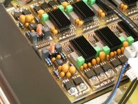
I added a photograph of the passive I/V, it's a module that can be placed instead of the dual OPA627 module, so both options OP-amp I/V and passive I/V can be used with the existing PCB. The module contains a dual copper wire I/V resistor (2 X 15 Ohm). The dual copper wire resistor is wound on a small plexiglass tube that is mounted on a IC socket. Due to the mobius loop the resistors have zero inductance.
Yesterday I had some more time to listen to the octal D-I DAC with passive I/V, the results are stunning, I never had this sound quality before, the sound seems to have infinite resolution, it's very transparent. Mid's are full and warm, bass is more accurate then before. Even more details are appearing from recordings, sound completely emerges from the speakers. Then consider I am only using OP-amp output at the moment as the tube output amplifier needs to be modified (higher gain). Can't wait to hear it in mixed mode.
Thanks for your reply [post#998]
Are you referring to op-amps like the OPA1632? well I haven't tried them yet, but I will. With the passive I/V circuit I only need a one OPA627 or OPA637 for each channel.
The tube amplifier with differential inputs connects directly to the I/V converters, the op-amp amplifier with differential inputs connects to the I/V converters as well.
I added a photograph of the passive I/V, it's a module that can be placed instead of the dual OPA627 module, so both options OP-amp I/V and passive I/V can be used with the existing PCB. The module contains a dual copper wire I/V resistor (2 X 15 Ohm). The dual copper wire resistor is wound on a small plexiglass tube that is mounted on a IC socket. Due to the mobius loop the resistors have zero inductance.
Yesterday I had some more time to listen to the octal D-I DAC with passive I/V, the results are stunning, I never had this sound quality before, the sound seems to have infinite resolution, it's very transparent. Mid's are full and warm, bass is more accurate then before. Even more details are appearing from recordings, sound completely emerges from the speakers. Then consider I am only using OP-amp output at the moment as the tube output amplifier needs to be modified (higher gain). Can't wait to hear it in mixed mode.
Attachments
I don't understand how you can have differential output using one OPA627 per channel. If I understand correctly, you're saying the I/V conversion is passive (using resistor), and then the OPA627 is used for a gain stage, correct? OPA627 only has one output, right? Do you mean you are using OPA627 as a differential amplifier, to convert balanced to single-ended? Could you please explain this, or better yet, post a schematic of the passive I/V section? I want to make sure you understand that I am not being critical here. I just don't understand what you're describing.
Hi tubee
Are you going to buy (parts) of the kit and build this DAC?
Erik
tubee said:Guido Tent has build a new dac. With resisrtor I/V and tube amplification. I have a 6922 waiting to be used for the same task.
Are you going to buy (parts) of the kit and build this DAC?
Erik
Hi John
I didn't actively show my face around for a long time, but all this time I accompanyed the thread and the evolution of the DAC. Your positive experience with passive IV conversion gives me new ideas for the output stage, as I am quiet a noob and do not have any experience with active IV conversion.
So you are using two 15R resistors per channel (one for + and one for -) and amplifying this with the OPA627? Have you added any low pass filter, or isn't this required with this DAC arrangement?
Hope to see the PCB's ready, but actually I have some other project to conclude too, so I can wait!
Erik
ezkcdude said:I don't understand how you can have differential output using one OPA627 per channel. If I understand correctly, you're saying the I/V conversion is passive (using resistor), and then the OPA627 is used for a gain stage, correct? OPA627 only has one output, right? Do you mean you are using OPA627 as a differential amplifier, to convert balanced to single-ended? Could you please explain this, or better yet, post a schematic of the passive I/V section? I want to make sure you understand that I am not being critical here. I just don't understand what you're describing.
As on radio,"If you've just tuned in,welcome".Let's not disturb Ecdesign with trivial details and let the big boy play.(Just kidding)
FYI the I/V stage has 3 X OPA627 per channel.
tubee said:Guido Tent has build a new dac. With resisrtor I/V and tube amplification. I have a 6922 waiting to be used for the same task.
If you want to use a Tube, I remember a comment from KYW about using the 2mA DC offset as a bias for the tube.
I think it's worth the try, but I haven't seen anyone here giving some feedback about it.
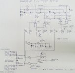
Passive I/V diagrams
Hi ezkcdude,
Thanks for your reply [post#1007]
The octal D-I DAC has single ended outputs, but uses differential inputs. There are two DAC groups one inverted and one non-inverted, so there is only one OP-amp necessary to combine both differential inputs from the passive I/V stage to the single ended output. I added a schematic diagram. As can be seen, with the D-I system there is no analog filter on the output. The special constuction of the combined zero inductance copper wire I/V resistor is absolutely necessary in order to obtain this level of sound quality.
Attachments
Re: Passive I/V diagrams
Thanks, that's kind of what I figured. I'm actually using almost exactly the same I/V stage in my DAC, except the capacitor is placed across the two signals. It's nice to hear it sounds good for you. In order for this to work well, the resistor pairs much be matched very closely, but I'm sure you know this already.
-ecdesigns- said:Hi ezkcdude,
Thanks for your reply [post#1007]
The octal D-I DAC has single ended outputs, but uses differential inputs. There are two DAC groups one inverted and one non-inverted, so there is only one OP-amp necessary to combine both differential inputs from the passive I/V stage to the single ended output. I added a schematic diagram. As can be seen, with the D-I system there is no analog filter on the output. The special constuction of the combined zero inductance copper wire I/V resistor is absolutely necessary in order to obtain this level of sound quality.
Thanks, that's kind of what I figured. I'm actually using almost exactly the same I/V stage in my DAC, except the capacitor is placed across the two signals. It's nice to hear it sounds good for you. In order for this to work well, the resistor pairs much be matched very closely, but I'm sure you know this already.
Attachments
Hi Erik
I want to use the six to seven 1541A's i have here, and still think about to implement them simple with a passive tubed I/V. For an octal dac will have to get 2 A's extra. PCM1704 (or PCM63) is not a bad choice either!
Nice idea Bricolo, to use the 2mA as tube-bias too. Will search this out.
I want to use the six to seven 1541A's i have here, and still think about to implement them simple with a passive tubed I/V. For an octal dac will have to get 2 A's extra. PCM1704 (or PCM63) is not a bad choice either!
Nice idea Bricolo, to use the 2mA as tube-bias too. Will search this out.
tubee said:Hi Erik
I want to use the six to seven 1541A's i have here, and still think about to implement them simple with a passive tubed I/V. For an octal dac will have to get 2 A's extra. PCM1704 (or PCM63) is not a bad choice either!
Nice idea Bricolo, to use the 2mA as tube-bias too. Will search this out.
it's not my idea
but I found the thread I was thinking abouthttp://www.diyaudio.com/forums/showthread.php?s=&postid=409375&highlight=#post409375
http://www.diyaudio.com/forums/showthread.php?s=&postid=349480&highlight=#post349480
-ecdesigns- said:Hi stefanobilliani,
Thanks for your reply [post#998]
Are you referring to op-amps like the OPA1632? well I haven't tried them yet, but I will.
Yes OPA1632 ,
Fully differential Audio op amp (pdf)
Dac's 2 mA biasing 6922
Hi Bricolo/Bob
Found this too:
http://www.diyaudio.com/forums/showthread.php?threadid=40416
But what happens when there are 8 dacs parallel?
John, i am interested to "turn" some of those twisted self made resistors too, are they relatively easy to make?
Hi Bricolo/Bob
Found this too:
http://www.diyaudio.com/forums/showthread.php?threadid=40416
But what happens when there are 8 dacs parallel?
John, i am interested to "turn" some of those twisted self made resistors too, are they relatively easy to make?
Copper wire resistor construction
Hi Tubee,
Thanks for your reply [post#1018]
When using 8 DAC's in parallel there will be a total of 8*4mA=32mA, this could cause problems with the described circuit. I use differential operation to cancel DC offset voltage, so I can't use that setup. Also keep in mind that a tube faillure could cause all TDA1541A's connected to be permanently damaged.
As I previously noted, the sound quality seems to improve with passive I/V setup, however there is a down side, impulse response time is affected. The very short attack time obtained with the op-amp I/V is missing, so a very smooth laid-back sound is produced. This could be caused by either the limited bandwith of the OPA627 when using higher gains or the relatively high I/V resistor value (18 Ohms instead of the calculated 6.25 Ohms). So I plan to experiment with the OPA1632 (180 MHz gain band width and 0.000022% distortion).
Problem with passive I/V remains the limited allowed voltage drop across the I/V resistor. When using a single TDA1541A DAC it's specified at 25mV, I am still not sure if this voltage can be much higher when using multiple DAC's in parallel as there is nothing mentioned about this in the philips datasheets. Suppose this voltage can be higer proportional to the amount of DAC's in parallel, this would mean that when using 4 DAC's in parallel, maximum voltage could be 100mV. With 4*4=16mA full scale current, the maximum I/V resistor value would be about 6.25 Ohm. If total output voltage of the differential DAC outputs is 2*100mV=200mVpp, then we need a gain of 14.14 in order to obtain 1Vrms output signal. This gain can be achieved without much problems, provided the amplifier circuit used has sufficient bandwidth.
Roll your own copper wire resistors, well it's quite easy, first you need very thin enamelled copper wire (I used wire from a 110V relay). It has about 9 Ohms / meter, in order to determine the resistance of the wire you want to use, cut off a 2m piece and measure the exact resistance, now you can calculate the total length of copper wire needed for a specific resistance. Let's assume you need 78cm for a 6.8 Ohm resistor, next you need to construct a mobius loop to eliminate inductance, all you have to do is fold the wire halfway (at 39 cm in this example). Then twist the 2 wires together (like a twisted pair in a network cable). Next wind the wire on a round piece of plastic or wood, first fixate the end that is folded, then complete the winding. Fixate the winding when completed. The 2 separate wires are the resistor connections, check with a ohm meter if the resistance value is correct. If you make the wire a bit longer, you can exactly calibrate the resistance value after winding, by cutting off small pieces of wire until the exact resistance value is obtained.
Advantages of copper wire resistors are: non magnetic material, very low noise, very low inductance and high resolution.
A good value to start with is around 6.25 Ohms, when using thin copper wire, estimated wire length is about 70cm (35cm when folded).
- Home
- Source & Line
- Digital Line Level
- Building the ultimate NOS DAC using TDA1541A