-ecdesigns-:
also, would it be possible to get the PCB dimensions for the 3 DI16 pcbs, as well as a description of what the cable assembly entails? Finally, I'm assuming that the part list is available once I place my order?
Oh and one more thing") I've read through some of this thread, but definitely not the entire thing. Are there any upgrades / modifications to the DI16 that I should consider / plan for?
I've read through some of this thread, but definitely not the entire thing. Are there any upgrades / modifications to the DI16 that I should consider / plan for?
Thanks!
also, would it be possible to get the PCB dimensions for the 3 DI16 pcbs, as well as a description of what the cable assembly entails? Finally, I'm assuming that the part list is available once I place my order?
Oh and one more thing
I've read through some of this thread, but definitely not the entire thing. Are there any upgrades / modifications to the DI16 that I should consider / plan for?Thanks!
Re: NOS DAC filter / reclocker
Hello John
Good filter for a non-os dac, what are the phase and transient response of this filter ?
Have you try a Bessel version ?
Thank you
Gaetan
-ecdesigns- said:Hi philpoole,
Thanks for your reply [post#934]
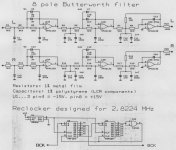
The aliasing can be attenuated, by using a 8th order Butterworth filter (I attached the schematic diagram).
Now imagine the sound you got now, without the alising disturbance. The octal D-I DAC now compares to that setup as the NOS-DAC with a single TDA1541A compares to your modded Marantz CD63. You must have heared it to understand why I choose this setup.
I have a reclock circuitry now, (also on the attached schematic), that can be used separately to remove the effects of continuous jitter from BCK without complicated setups. It's the serial shiftregister reclocker, it uses a 48MHz clock module to reclock, when put in the DAC you can throw almost any continuous jitter affected signal at it, and it would still sound natural and open. The reclocker uses 4 components, power supply bypass components excluded. The unused SN74F00 inputs should be connected to GND. It's not expensive and I think you could give it a try, and let your ears decide.
Cheers,
John
Hello John
Good filter for a non-os dac, what are the phase and transient response of this filter ?
Have you try a Bessel version ?
Thank you
Gaetan
Attachments
Hi luvdunhill,
- PCM2706 / PCM2707 (USB interfaces that can output I2S), including the USB interface from DDDAC.
- I2S output of SPDIF audio receivers CS8412, CS8414, CS8416 (set for I2S), this enables connecting most SPDIF sources.
- I2S output of the squeezebox (glue logic required).
- I2S outputs of CD transports that output Philips format 64BCK/WS.
DI16CORE PCB: 19 x 11,6 cm (7.48" x 4.567")
DI16PS PCB: 11,1 x 10,1 cm (4.37" x 3.976")
USBDI2S PCB: 17,8 x 3,7 cm (7" x 1.4667")
I still need to make some drawings of both DI 8(M) and DI 16 cable assemblies. I will put them on my website when ready.
You can download the assembly instructions, there you will find the components used. I can also email both parts-list and schematics if desired.
The following upgrades / modifications are possible:
USBDI2S module:
- Low jitter 48 MHz master clock (<1ps RMS jitter).
- 330uF/6V tantalium decoupling cap for the master clock power supply.
- Shiftregister reclocker reset circuit timing correction (3.3 ... 33pF capacitor)
- Lower resistance values for the IC power supply series resistors (already modified on new USBDI2S modules)
- SN74HC161 instead of SN74F163 (lower masterclock load)
- Copper foil screening of the ICs to reduce HF EMI emitted / picked-up by the ICs.
DI16CORE:
- Current sources / 4K7 resistors for pulling the LM4562 OP-amps into class A (current sources are preferred).
- 8 * 3 configuration (24 * TDA1543 in total)
- 0.1% low TC resistors / bulk metal foil resistors for I/V, diff amp and output attenuator.
- External Tubediff stage for reducing thermal memory distortion of the diff amp.
- Copper foil screening of the ICs to reduce EMI emitted / picked-up by the ICs.
DI16PS:
- 25VA toroidial transformer for 8 * 3 version.
I would like to answer the above with a question. What I2S sources are known to work with the DI DACs?
- PCM2706 / PCM2707 (USB interfaces that can output I2S), including the USB interface from DDDAC.
- I2S output of SPDIF audio receivers CS8412, CS8414, CS8416 (set for I2S), this enables connecting most SPDIF sources.
- I2S output of the squeezebox (glue logic required).
- I2S outputs of CD transports that output Philips format 64BCK/WS.
also, would it be possible to get the PCB dimensions for the 3 DI16 pcbs, as well as a description of what the cable assembly entails? Finally, I'm assuming that the part list is available once I place my order?
DI16CORE PCB: 19 x 11,6 cm (7.48" x 4.567")
DI16PS PCB: 11,1 x 10,1 cm (4.37" x 3.976")
USBDI2S PCB: 17,8 x 3,7 cm (7" x 1.4667")
I still need to make some drawings of both DI 8(M) and DI 16 cable assemblies. I will put them on my website when ready.
You can download the assembly instructions, there you will find the components used. I can also email both parts-list and schematics if desired.
Oh and one more thing I've read through some of this thread, but definitely not the entire thing. Are there any upgrades / modifications to the DI16 that I should consider / plan for?
The following upgrades / modifications are possible:
USBDI2S module:
- Low jitter 48 MHz master clock (<1ps RMS jitter).
- 330uF/6V tantalium decoupling cap for the master clock power supply.
- Shiftregister reclocker reset circuit timing correction (3.3 ... 33pF capacitor)
- Lower resistance values for the IC power supply series resistors (already modified on new USBDI2S modules)
- SN74HC161 instead of SN74F163 (lower masterclock load)
- Copper foil screening of the ICs to reduce HF EMI emitted / picked-up by the ICs.
DI16CORE:
- Current sources / 4K7 resistors for pulling the LM4562 OP-amps into class A (current sources are preferred).
- 8 * 3 configuration (24 * TDA1543 in total)
- 0.1% low TC resistors / bulk metal foil resistors for I/V, diff amp and output attenuator.
- External Tubediff stage for reducing thermal memory distortion of the diff amp.
- Copper foil screening of the ICs to reduce EMI emitted / picked-up by the ICs.
DI16PS:
- 25VA toroidial transformer for 8 * 3 version.
I wonder if the cheap USB soundcard incorporates an PCM2706/7
An externally hosted image should be here but it was not working when we last tested it.
-ecdesigns- said:- I2S output of SPDIF audio receivers CS8412, CS8414, CS8416 (set for I2S), this enables connecting most SPDIF sources.
wouldn't the Wolfson 8804 qualify?
-ecdesigns- said:- I2S outputs of CD transports that output Philips format 64BCK/WS.
ah, so is there a general rule of thumb on what transports qualify? I'm assuming all of the Philips transports, what about the Japanese assemblies (Teac, Esoteric, Sony, etc.)? Any specific recommendation on a cheap (and perhaps another recommendation on the not-so-cheap top-performer) transport that could be modified to expose the i2s and would perform well with both your DACs?
Thanks again!
The Wolfson qualifies, it is mentioned in the data sheets.
There is a difference between Sony and Philip format, but for a Sony/Teac transport you can use John's special SPdif adapter which reclocks data and works pretty well.
I have joined this thread just a few weeks ago. I think it is important to go through all the pages, even if John does not get tired answering the same questions over and over again. It would be best for him to write a white paper of all his work in his own pages. I am thinking about ordering this dac with the tda1541, but I am still not sure how it sounds compared to the top, I had the chance to listen to a Weiss Medea at home. If you have time to build it yourself with the boards, this dac is of no risk.
It is a pity, but mainstream magazines just test what they advertise, so no chance for John. There is also an idea that comes from Hoerwege, Germany. There you can hire a finished dac, so you can listen to it at home to build up your own opinion. This would be a solution for Europe at least. Because John is a trustworthy person, I would also believe him, if he could compare his dac to the top, but as far as I know, there has always been just a contest against his simple TDA1541 dac.
For example, Zanden is one of the best, it has just 2 TDA1541a, but a very special output filter. John, if you have a chance to get a Zanden or another high quality dac for a short while, please report.
Shame on me!
Due to heavy work last couple of weeks I did not find the energy to make this simple mod...shame, shame...it took two minutes to swap the 48Mhz clock from the USB module for the...how do we call it?
...or ultra low jitter? anyway this is surely a great mod I was listening to some Vivaldi's concertos for violin and strings, L'Europa Galante/Fabio Biondi and it was obvious that the instrumental definition and textures increased, that the secondary melodies were better delineated and maybe the midbass was more punchy. Massive string attacks are better, faster, now.
The DAC is sounding more analog-like.
John, are you our Digital Messiah?
I know you are but we need proof!
Many thanks
M
Due to heavy work last couple of weeks I did not find the energy to make this simple mod...shame, shame...it took two minutes to swap the 48Mhz clock from the USB module for the...how do we call it?
- Low jitter 48 MHz master clock (<1ps RMS jitter).
...or ultra low jitter? anyway this is surely a great mod
I was listening to some Vivaldi's concertos for violin and strings, L'Europa Galante/Fabio Biondi and it was obvious that the instrumental definition and textures increased, that the secondary melodies were better delineated and maybe the midbass was more punchy. Massive string attacks are better, faster, now. The DAC is sounding more analog-like.
It is a pity, but mainstream magazines just test what they advertise, so no chance for John. There is also an idea that comes from Hoerwege, Germany. There you can hire a finished dac, so you can listen to it at home to build up your own opinion. This would be a solution for Europe at least. Because John is a trustworthy person, I would also believe him, if he could compare his dac to the top, but as far as I know, there has always been just a contest against his simple TDA1541 dac.
John, are you our Digital Messiah?
I know you are but we need proof!
Many thanks
M
DI8M dac from John
Hi All
3 days ago I finished this di8m dac.
Latest modifications (low jitter clock Dem clock spdifmodule usb module)
I/V is opamp (no Tubes) LM4562.
XLR balanced output.
8x TDA1541a S1 single crown (dc ofsett after tuning < 0.3 mv !!)
I use NAD 218 THX (modified !!) on Magnepans M3
no preamp but 2x balanced DACT CT-2 stepped attenuator (10kohm)
The only thing I can say is that this dac outperforms every dac I made and every other dac I have heard.
This beast is not to beat !!
If someone wants to listen here in Rotterdam he (she) is welcome !
Onno (Onnosr)
Hi rolls,
The DI 8M has also be compared with a North Star CD transport with 192 KHz / 24 bit upsampling option & Lyngdorf digital power amp with room perfect module. The DI 8M outperformed it by a large margin, it had much better detail, wider soundstage and more analog / natural sound.
I also compared the DI DACs with a Philips SACD1000 player, both DI 16 and DI 8M easily outperformed it.
http://6moons.com/audioreviews/zanden/mkII.html
quote
"Explains Yamada-San that standard digital low-pass filters start to phase shift at 1kHz and exceed 30-degree rotation at 20kHz, contributing to the somewhat harsh, brittle high end of digital when compared to analogue. His 'bridged-T fixed-impedance filter' is used predominantly in deep-sea telephone cables but here uniquely implemented for audio use
The filter is a passive bridged-T filter with fixed impedance, it is claimed to have linear phase response in the passband."
If I am correct digital (FIR) filters are phase linear unlike analog (IIR) filters. Simulations using the TI FilterPro software showed that all analog filters with a turnover frequency of approx. 20 KHz already started to shift phase at 1 KHz. There are many factors causing the "digital / synthetic" sound quality, it's not only the filter.
I prefer a true linear phase interpolation filter, instead of a modified deep-sea telephone line filter, filled with inductors and capacitors.
I already get nervous when I have to use a single coupling cap in the signal path, as I know too well what effect it can have on sound quality, and how difficult it is to get similar performance as a DC coupling. Inductors / transformers are even worse, and only the very best quality types will do. For now I have problems enough with resistors.
I am not sure about the amount of DAC chips used in the van Zanden DAC, but I read it was a TDA1541A-S2 chip:
quote:
"1985-issue Philips TDA-1541A "Double-Crown" 16/44 chip"
Based on the technical information I was able to collect about the van Zanden 5000 Mk.IV, I am pretty confident that the DI 8M will be able to outperform it.
if he could compare his dac to the top, but as far as I know, there has always been just a contest against his simple TDA1541 dac.
The DI 8M has also be compared with a North Star CD transport with 192 KHz / 24 bit upsampling option & Lyngdorf digital power amp with room perfect module. The DI 8M outperformed it by a large margin, it had much better detail, wider soundstage and more analog / natural sound.
I also compared the DI DACs with a Philips SACD1000 player, both DI 16 and DI 8M easily outperformed it.
For example, Zanden is one of the best, it has just 2 TDA1541a, but a very special output filter. John, if you have a chance to get a Zanden or another high quality dac for a short while, please report.
http://6moons.com/audioreviews/zanden/mkII.html
quote
"Explains Yamada-San that standard digital low-pass filters start to phase shift at 1kHz and exceed 30-degree rotation at 20kHz, contributing to the somewhat harsh, brittle high end of digital when compared to analogue. His 'bridged-T fixed-impedance filter' is used predominantly in deep-sea telephone cables but here uniquely implemented for audio use
The filter is a passive bridged-T filter with fixed impedance, it is claimed to have linear phase response in the passband."
If I am correct digital (FIR) filters are phase linear unlike analog (IIR) filters. Simulations using the TI FilterPro software showed that all analog filters with a turnover frequency of approx. 20 KHz already started to shift phase at 1 KHz. There are many factors causing the "digital / synthetic" sound quality, it's not only the filter.
I prefer a true linear phase interpolation filter, instead of a modified deep-sea telephone line filter, filled with inductors and capacitors.
I already get nervous when I have to use a single coupling cap in the signal path, as I know too well what effect it can have on sound quality, and how difficult it is to get similar performance as a DC coupling. Inductors / transformers are even worse, and only the very best quality types will do. For now I have problems enough with resistors.
I am not sure about the amount of DAC chips used in the van Zanden DAC, but I read it was a TDA1541A-S2 chip:
quote:
"1985-issue Philips TDA-1541A "Double-Crown" 16/44 chip"
Based on the technical information I was able to collect about the van Zanden 5000 Mk.IV, I am pretty confident that the DI 8M will be able to outperform it.
pffffffffff
I would never dare to predict how a component sounds from schematic or review....
The literature about the Zanden DAC is a bit confusing but what I understand the 'bridged-T fixed-impedance filter" is only used for deemphasis....
The Zanden patent descibes it more accurate providing a notch filter for every conceivable aliasing image. The disadvantage is those filters produce severe ringing.... Pedja posted some simulations on this forum.
Re: Op-amp class A bias circuits
ah, I finally found the schematics in Post #1201 for the class A biasing. I'm assuming the D16core PCB doesn't have provision for the cascode bias, so it will have to be airwired. Any pictures?
For the 2sk117, will the 2sk170 work as well, and if so, any preference on the grade (BL, GR, etc.)
Thanks!
-ecdesigns- said:Post #1201
ah, I finally found the schematics in Post #1201 for the class A biasing. I'm assuming the D16core PCB doesn't have provision for the cascode bias, so it will have to be airwired. Any pictures?
For the 2sk117, will the 2sk170 work as well, and if so, any preference on the grade (BL, GR, etc.)
Thanks!
I see here in this post http://www.diyaudio.com/forums/showthread.php?postid=1223474#post1223474
the principle used to implement a 1541A DEM Clock. I'd like to make a test with my simple 1541A DAC used in conjonction with an SA7220B. In that case, BCK is about 5.6448 Mhz.
So The maybe silly question (may be off topic) is just "how to obtain 352.8 KHz using 74HC161 as it should be divided into 16x " ?
the principle used to implement a 1541A DEM Clock. I'd like to make a test with my simple 1541A DAC used in conjonction with an SA7220B. In that case, BCK is about 5.6448 Mhz.
So The maybe silly question (may be off topic)
is just "how to obtain 352.8 KHz using 74HC161 as it should be divided into 16x " ?OP-amp bias circuit
Hi luvdunhill,
Yes the DI16C PCB hasn't got provisions for the class A biassing circuits, so they have to be air wired, or small bias PCB modules can be used, like posted earlier on this thread
The 2SK170 should work as well, other N-channel JFETs like the 2SK246 can be used too.
IDSS classification:
Y, 1.2 ... 3mA
GR, 2.6... 6.5mA
BL, 6 ... 14mA
Depending on IDSS classification / tolerances in IDSS, the current programming resistor value needs to be changed, in order to obtain the desired output current (3...4mA).
Hi luvdunhill,
ah, I finally found the schematics in Post #1201 for the class A biasing. I'm assuming the D16core PCB doesn't have provision for the cascode bias, so it will have to be airwired. Any pictures?
Yes the DI16C PCB hasn't got provisions for the class A biassing circuits, so they have to be air wired, or small bias PCB modules can be used, like posted earlier on this thread
For the 2sk117, will the 2sk170 work as well, and if so, any preference on the grade (BL, GR, etc.)
The 2SK170 should work as well, other N-channel JFETs like the 2SK246 can be used too.
IDSS classification:
Y, 1.2 ... 3mA
GR, 2.6... 6.5mA
BL, 6 ... 14mA
Depending on IDSS classification / tolerances in IDSS, the current programming resistor value needs to be changed, in order to obtain the desired output current (3...4mA).
-ecdesigns- said:Hi tubee,
This is good news as it shows that it's possible to achieve identical sound quality from two completely different digital sound sources (I used an old 500 MHz iMac for USB, and a very old Sony CD player with SPDIF coax output). The test CD was ripped and imported in iTunes, then placed in the Sony transport.
Sorry to bring up an old post of yours, but I am a bit puzzled.
I went the computer transport route because I could not get past a certain quality with regular transports no matter how many tweaks from the various suggestions posted on many forums, I tried. The excellent Pioneer stable platter at least could not keep up with my USB PCM2707 transport. ( I have no money to try boutique stuff like Teac).
Now you are stating that a cheap Sony player
as transport sounded as good as your USB/I2S approach.
This makes me wonder if your PCM2707 circuitry has a problem
somewhere? I have seen a schematic of your reclocker applied
to the PCM2707 and there you are running the chip in bus powered mode. Is there a reason you do this?
I was not able to get the same quality output in bus powered mode, then in self powered mode.
Don't understand me wrong, I am not trying to criticize you, or your work. I am just wondering why we achieved so different results with
the same chip. John Swensson was probably the first among the DIYers that used the PCM2707 and he also stated how much better it was than any regular transport he used.
Cheers,
Klaus
Hi Radian.
As noted earlier on this thread, I think two criteria must be met in order to achieve optimal performance when using digital sound sources:
1) Data must be bit correct, or at least with as few errors as possible. Most CD, CDROM, DVD transports will manage to output the correct data (after CRC correction), regardless if they are cheap units like the ones used in computers, or expensive High-end transports.
2) Jitter frequency components that cause audible sound quality degradation must be kept as low as possible. I think this is one of the key factors that causes most audible differences between transports.
Standard PCM2706 / PCM2707 based designs don't have a reclocker, now timing jitter amplitude and spectra depends fully on PLL stability, crosstalk, noise, interference, PCB lay-out and so on. So it's really no wonder that sound quality comes in all flavours.
I simply accepted the fact that I2S outputs do contain (significant) jitter. Both BCK and DATA originate from the same chip, so there will also be DATA related jitter on BCK, even with a low jitter PLL.
I solved the problem radically, by using a shiftregister reclocker with 48 MHz low jitter crystal oscillator (<1ps rms). The master clock is fixed, so it can't pick-up interference from a voltage control input like with a VCXTO. The shiftregister reclocker "locks" to the incoming BCK timing signal by a forced-reset scheme. The circulating bit pattern provides the actual timing signal. The circulating speed is determined by the low jitter clock. The forced reset enables the shiftregister to get the best possible lock on the next positive going edge of the BCK input signal.
In order to make absolutely sure that the shiftregister reclocker could match or exceed a synchronously reclocked timing signals from a CD player, both were compared, using the same music fragments / tracks. It turned out that the shiftregister reclocker (while placed close to the DAC chips) easily outperformed the synchronously reclocked I2S signal from the CD player.
When the direct I2S output from the PCM2706 was used (no reclocking), the CD player with I2S output outperformed it.
Recently I used the same trick with the good old CS8212 SPDIF receiver, by adding the shiftregister reclocker, and making sure the SPDIF receiver got the correct data, performance was on the same high level as with the USBDI2S module.
There is nothing wrong with the PCM2706 circuitry, I just met both criteria, bit correct data, and low jitter. The use of the shiftregister reclocker is the main reason why I could get similar high performance from a cheap Sony CD player. It also turned out that the Sony CD player has an integrated RAM buffer (anti-shock memory), so from this I could conclude that multiple re-reads should be possible, and even severe read problems (external mechanical vibrations) can still be corrected to some extent.
It's only better if jitter is low enough, now that is possible, I fully agree with John Swenson.
Beside the sound quality, using a computer as digital sound source offers a lot of advantages.
Cheers,
John
Don't understand me wrong, I am not trying to criticize you, or your work. I am just wondering why we achieved so different results with
the same chip
As noted earlier on this thread, I think two criteria must be met in order to achieve optimal performance when using digital sound sources:
1) Data must be bit correct, or at least with as few errors as possible. Most CD, CDROM, DVD transports will manage to output the correct data (after CRC correction), regardless if they are cheap units like the ones used in computers, or expensive High-end transports.
2) Jitter frequency components that cause audible sound quality degradation must be kept as low as possible. I think this is one of the key factors that causes most audible differences between transports.
Standard PCM2706 / PCM2707 based designs don't have a reclocker, now timing jitter amplitude and spectra depends fully on PLL stability, crosstalk, noise, interference, PCB lay-out and so on. So it's really no wonder that sound quality comes in all flavours.
I simply accepted the fact that I2S outputs do contain (significant) jitter. Both BCK and DATA originate from the same chip, so there will also be DATA related jitter on BCK, even with a low jitter PLL.
I solved the problem radically, by using a shiftregister reclocker with 48 MHz low jitter crystal oscillator (<1ps rms). The master clock is fixed, so it can't pick-up interference from a voltage control input like with a VCXTO. The shiftregister reclocker "locks" to the incoming BCK timing signal by a forced-reset scheme. The circulating bit pattern provides the actual timing signal. The circulating speed is determined by the low jitter clock. The forced reset enables the shiftregister to get the best possible lock on the next positive going edge of the BCK input signal.
In order to make absolutely sure that the shiftregister reclocker could match or exceed a synchronously reclocked timing signals from a CD player, both were compared, using the same music fragments / tracks. It turned out that the shiftregister reclocker (while placed close to the DAC chips) easily outperformed the synchronously reclocked I2S signal from the CD player.
When the direct I2S output from the PCM2706 was used (no reclocking), the CD player with I2S output outperformed it.
Now you are stating that a cheap Sony player
as transport sounded as good as your USB/I2S approach.
This makes me wonder if your PCM2707 circuitry has a problem
Recently I used the same trick with the good old CS8212 SPDIF receiver, by adding the shiftregister reclocker, and making sure the SPDIF receiver got the correct data, performance was on the same high level as with the USBDI2S module.
There is nothing wrong with the PCM2706 circuitry, I just met both criteria, bit correct data, and low jitter. The use of the shiftregister reclocker is the main reason why I could get similar high performance from a cheap Sony CD player. It also turned out that the Sony CD player has an integrated RAM buffer (anti-shock memory), so from this I could conclude that multiple re-reads should be possible, and even severe read problems (external mechanical vibrations) can still be corrected to some extent.
John Swensson was probably the first among the DIYers that used the PCM2707 and he also stated how much better it was than any regular transport he used.
It's only better if jitter is low enough, now that is possible, I fully agree with John Swenson.
Beside the sound quality, using a computer as digital sound source offers a lot of advantages.
Cheers,
John
Thank you so much John,
you are an amazing guy:
You freely share your highly sophisticated designs with other diyers and on top of that you explain in detail why you do what you do,
in the least defensive way I have seen.
You are one of a kind and I wish you leaps of success with your designs.
P.S.
I would still suggest trying the PCM2707 in self powered mode to see for yourself if the junk of the USB power is affecting the sound or not.
Cheers,
Klaus
Radian wrote:
I fully agree
For those lucky enough who are considering DI8, I found a source for which appear to be good and cheap TDA1541A chips, very near:
http://www.diyaudio.com/forums/showthread.php?threadid=105354&pagenumber=2
There is a special price for 8 units
Cheers
M
you are an amazing guy:
I fully agree
For those lucky enough who are considering DI8, I found a source for which appear to be good and cheap TDA1541A chips, very near:
http://www.diyaudio.com/forums/showthread.php?threadid=105354&pagenumber=2
There is a special price for 8 units
Cheers
M
Reclocking
I use "self powered" mode in my own PCM2706 DAC. I found reclocking improved the sound when using MUR860 diodes in the DAC's power supply.
Now I use Onsemi MSR860 diodes because they sound better and now reclocking isn't an improvement. I haven't given up on reclocking, but currently I am not using it.
From this simple change in diodes I conclude that self powered mode may be as good as reclocked and not everyone will see the same results unless the parts and layout is exactly the same.
Cheers,
Brent
- Home
- Source & Line
- Digital Line Level
- Building the ultimate NOS DAC using TDA1541A