Re: Plating PCB
ecdesigns... when I say "you start to see the gold colour when you start to solder" I mean to say that you start to see the gold colour in contrast to the silver colour of the solder. The gold doesn't mix into the solder.
A board manufacturer www.4pcb.com replied to my question about Flash Gold today and he says that there is a layer of Nickel in their Flash Gold finish. I have two versions of my board one Flash Gold and one not. They sound the same to me. Flash Gold is very nice to work with. SMD parts need a flat surface like Gold Flash provides.
Filters
Hi Bernhard,
Thanks for your reply [post#780]
I tried adding filters to the octal D-I DAC during development (8th order Butterworth filter and a 2nd order Bessel filter) But the sound was more natural without filters. I used the filterless octal D-I DAC with my set for quite some time now, even at high volume settings, and no HF related problems have occured, not with the control amplifier, not with the cascode power amplifier and not with the sonic resonators. Higher frequency sound quality is crystal clear.
I didn't try transformers yet, but I am pretty sure you have") . I saw your DAC test setup, both transformers and filters included. I respect people who take the effort to build, test and improve projects in practice. I am very interested and have some questions:
. I saw your DAC test setup, both transformers and filters included. I respect people who take the effort to build, test and improve projects in practice. I am very interested and have some questions:
- How did you interface the PCM56 to the CS8412, especially WS
- How is the CS8412 used, are the output's synchronously reclocked?
- What brand transformers did you use?
- What are the filter characteristics?
- How does this setup compare to a op-amp based I/V?
Hi Bernhard,
Thanks for your reply [post#780]
I tried adding filters to the octal D-I DAC during development (8th order Butterworth filter and a 2nd order Bessel filter) But the sound was more natural without filters. I used the filterless octal D-I DAC with my set for quite some time now, even at high volume settings, and no HF related problems have occured, not with the control amplifier, not with the cascode power amplifier and not with the sonic resonators. Higher frequency sound quality is crystal clear.
I didn't try transformers yet, but I am pretty sure you have
. I saw your DAC test setup, both transformers and filters included. I respect people who take the effort to build, test and improve projects in practice. I am very interested and have some questions:- How did you interface the PCM56 to the CS8412, especially WS
- How is the CS8412 used, are the output's synchronously reclocked?
- What brand transformers did you use?
- What are the filter characteristics?
- How does this setup compare to a op-amp based I/V?
Re: Filters
There is only one inverter between CS and PCM chip.
No reclocking.
The transformers are salvaged from 2 equal pieces of old measurement equipment, response written on the equipment was or was better 20-20000Hz.
Don't know the characteristic, I only see how it smoothes the waveformes on the scope and FFT.
I did not listen to that setup with op amp, it sounds very good as is now, but there is a lot of new variables in this setup and it is difficult to say what might be responsible for sound:
Non os, passive I/V, transformer filtering.
But I think mostly it is Non os, because I have also a non os modified Sony 502ES II with good DAC chips and it sounds much the same.
The transformer does lot of things.
Phase reverse, step up, filtering, DC blocking.
By the way, do transformers need a resistive load on the secondary winding to be linear ?
Those had a high frequency boost that disappeared with 5k on secondary.
And about PCM56:
Without deglitcher even low level performance is very good *
Also it works good with passive I/V up to 1kohm
And it is a mono DAC, easy to select for triple crown
* better than TDA1541A thanks to MSB adjust
-ecdesigns- said:
- How did you interface the PCM56 to the CS8412, especially WS
- How is the CS8412 used, are the output's synchronously reclocked?
- What brand transformers did you use?
- What are the filter characteristics?
- How does this setup compare to a op-amp based I/V?
There is only one inverter between CS and PCM chip.
No reclocking.
The transformers are salvaged from 2 equal pieces of old measurement equipment, response written on the equipment was or was better 20-20000Hz.
Don't know the characteristic, I only see how it smoothes the waveformes on the scope and FFT.
I did not listen to that setup with op amp, it sounds very good as is now, but there is a lot of new variables in this setup and it is difficult to say what might be responsible for sound:
Non os, passive I/V, transformer filtering.
But I think mostly it is Non os, because I have also a non os modified Sony 502ES II with good DAC chips and it sounds much the same.
The transformer does lot of things.
Phase reverse, step up, filtering, DC blocking.
By the way, do transformers need a resistive load on the secondary winding to be linear ?
Those had a high frequency boost that disappeared with 5k on secondary.
And about PCM56:
Without deglitcher even low level performance is very good *
Also it works good with passive I/V up to 1kohm
And it is a mono DAC, easy to select for triple crown
* better than TDA1541A thanks to MSB adjust
EC,
I have a question regarding the current design of your PCBs:
Is the tubed output's PCB connected directly to the tube sockets? Or are the tube sockets wired to the PCB?
In other words, what type of tube socket does the current design use? PCB mounted (with pins) or 'free' (with solder lugs)?
Thanks!
Tube sockets
Hi adhoc,
thanks for your reply [post#784]
The tube sockets are high quality ceramic PCB types, the pin's are directly soldered to the printed circuit board / no wires, so connections are as short as possible. The sockets are in turn fixed to the aluminum chassis using fixating rings supplied with the tube sockets and hexagon threaded spacers that enable easy fixating. In addittion, the printed circuit board can be fixated to the chassis as well using spacers. Mounting holes are already provided on the PCB.
The tube output stage module is very easy to build. Solder lug type sockets can be used as well, then short solid wires can be used to adapt the solder lugs to the printed circuit board.
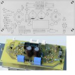
I added both a silkscreen plot and a photograph of the tube output stage printed circuit board, the PCB tube sockets and 3mm high-brightness status LED's are mounted on the solder side, all other components are mounted on the component side. This way there is enough space between the chassis and the printed circuit board. All connections are made trough PCB connectors, so the module can be removed very quickly.
Hi adhoc,
thanks for your reply [post#784]
The tube sockets are high quality ceramic PCB types, the pin's are directly soldered to the printed circuit board / no wires, so connections are as short as possible. The sockets are in turn fixed to the aluminum chassis using fixating rings supplied with the tube sockets and hexagon threaded spacers that enable easy fixating. In addittion, the printed circuit board can be fixated to the chassis as well using spacers. Mounting holes are already provided on the PCB.
The tube output stage module is very easy to build. Solder lug type sockets can be used as well, then short solid wires can be used to adapt the solder lugs to the printed circuit board.
I added both a silkscreen plot and a photograph of the tube output stage printed circuit board, the PCB tube sockets and 3mm high-brightness status LED's are mounted on the solder side, all other components are mounted on the component side. This way there is enough space between the chassis and the printed circuit board. All connections are made trough PCB connectors, so the module can be removed very quickly.
Attachments
Thanks for your reply EC.
The reason I asked that question was because I intend to mount the tubes horizontally (to fit low profile case - height around 2.2") and was wondering whether that was possible with your 'default' design. Now I know.
If there any other components that exceed 2" in height, it would be great if you could let me know as I intend to order the case soon. Thanks!
Housing dimensions
Hi adhoc,
thanks for your reply [post#786/787]
2" height could be a problem, transformers used in both power supplies probably won't fit. I placed the tube output modules above part of the analog mainboard, so that won't fit using 2" height. The 2mm thickness of the aluminum plates however is no problem, I used 2mm thick aluminum plates for most parts as well, exept for the sidepanels.
Maybe it's wise to wait with the housing, and check module dimensions first, I can measure the exact dimensions of each module if this could help. But a height of approx. 3" is the minimum. The grid around the tubes has a important function, screening, it helps to keep hum levels very low. Placing the tubes horizontally, close to other parts can cause oscillation. Long wires routed from the printed circuit board to tube sockets could have a similar effect.
EC,
Thank you for that reply.
I guess I must rein myself in, and stop being such an eager beaver. But it's difficult! Sometimes I can't help myself.
Would you be able to give us an estimated date of completion for the octal DAC? I do not mean to be rude, but I get the impressions that progress has slowed a bit recently.
I guess it's like waiting for Christmas - the last few days just seem to drag on forever...
Adhoc wrote:
LOL
As it is said, big men and children are only differenced by the price of their toys!
I wanted to say...me too!
[COLOR=dark red]I think it is time to open a thread that can be called "I am an obsessive-compulsive builder" [/COLOR] 
Good luck to all with your projects.
M
Would you be able to give us an estimated date of completion for the octal DAC? I do not mean to be rude, but I get the impressions that progress has slowed a bit recently.
I guess it's like waiting for Christmas - the last few days just seem to drag on forever...
LOL
As it is said, big men and children are only differenced by the price of their toys!
I wanted to say...me too!
[COLOR=dark red]I think it is time to open a thread that can be called "I am an obsessive-compulsive builder" [/COLOR]
Good luck to all with your projects.
M
Time to start ?
Hi adhoc,
thanks for your reply [post#789]
Octal D-I DAC progress may have been slowed down lately because of the time I spend optimizing (jitter) performance, another factor is that I still have to run my company as well and have to complete some urgent projects, so there is less time available for the octal D-I DAC at the moment.
But you are right, I can imagine some people have already gathered components and can't wait to start building.
So here is a possible solution,
I could start ordering the first batch of printed circuit boards for the octal D-I DAC core only. This is basically already a fully functional DAC.
The other printed circuit boards could follow later, when design / testing is completed.
The octal D-I DAC core consists of the following circuit boards:
Analog mainboard (1X)
DAC TDA1541A module (8X)
Autodetecting dual format timing-chain (1X), new module
I/V differential amplifier module (2X)
Ultra high speed clock buffer module (1X), new module
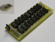
I added a photograph showing both new modules, the ultra high speed BCK buffer module and the new autodetecting dual format timing-chain module.
Hi adhoc,
thanks for your reply [post#789]
Octal D-I DAC progress may have been slowed down lately because of the time I spend optimizing (jitter) performance, another factor is that I still have to run my company as well and have to complete some urgent projects, so there is less time available for the octal D-I DAC at the moment.
But you are right, I can imagine some people have already gathered components and can't wait to start building.
So here is a possible solution,
I could start ordering the first batch of printed circuit boards for the octal D-I DAC core only. This is basically already a fully functional DAC.
The other printed circuit boards could follow later, when design / testing is completed.
The octal D-I DAC core consists of the following circuit boards:
Analog mainboard (1X)
DAC TDA1541A module (8X)
Autodetecting dual format timing-chain (1X), new module
I/V differential amplifier module (2X)
Ultra high speed clock buffer module (1X), new module
I added a photograph showing both new modules, the ultra high speed BCK buffer module and the new autodetecting dual format timing-chain module.
Attachments
Hi EC,
Although waiting is tough, I would like to wait until your whole project is completed and buy the whole kit at one time, including the housing. Actually, I might buy two kits from you
BTW, if I want to add more TDA1541As (more than 8), does the timing chain module require modification? In other words, do I need more than just extra DAC modules?
Just to make clear, is the PCB going to be dual sided, double thick copper trace with gold plating?
Thanks.
EC,
Wow - perhaps it was great that I asked on the estimated date of completion.
I'm a little unclear about the options available for the octal DAC.
Would I be correct to say that these are the 2 options you're offering?
1. complete DAC kit, all parts (except TDA1541A) and chassis included
2. bare PCBs, nothing else
Could you elaborate on which parts of the DAC design you not finalised? Just the USB receiver/convertor? You have me a little confused with your reference of 'core DAC'. Do you plan to add on an preamp/poweramp/headphone amp to your 'core DAC'?
I am also unsure as to what you mean by the '8x' behind 'DAC TDA1541A module' in your last post.
Thanks for putting up with my incessant questions!
To Everyone,
Last night I had a good long think about it, and I think that it would be best if we *all* waited for EC to finalise the entire design.
That way, we could order the PCBs in one massive batch, possibly lowering the final cost-per-PCB. Also, we could avoid any problems that would come with last-minute tweaks/changes which would result in some members getting different 'versions' of the board.
Hi,
yes, agree with you: group would be cheaper.
Some people already collecting parts and would buy only PCBs.
Or maybe also some parts which cant get them.
To sell complete DAC with all parts is of course up to John.
Production of tubes are available.
TDA1541A is more difficult to get. But for bigger quantity i believe, is easier to order.
I just wanted make easier for John.
It is dificult to guess, how many complete DI-DAC to make.
regards, Bostjan
hi john,
If U need large lots same date of 1541a, Pls email to me . I had 132pcs same date on hand. I an good offer to U.
thomas_siu@hotmail.com
If some john's dac lover I had around 150 pcs more different date code but can match 8 pcs per set.
thx
thomas
If U need large lots same date of 1541a, Pls email to me . I had 132pcs same date on hand. I an good offer to U.
thomas_siu@hotmail.com
If some john's dac lover I had around 150 pcs more different date code but can match 8 pcs per set.
thx
thomas
MGH said:Thomas (Tubelover) is a good guy. He has sent out the 8 TDA1541As I ordered from him - he told me they are all the same date code, so they should be well matched. But I think they are the most basic version, not even an R1.
R1 are the bad ones.
R1 are the bad ones.
R1 are the bad ones.
R1 are the bad ones.
R1 are the bad ones.
R1 are the bad ones.
R1 are the bad ones.
R1 are the bad ones.
R1 are the bad ones.
R1 are the bad ones.
R1 are the bad ones.
R1 are the bad ones.
R1 are the bad ones.
R1 are the bad ones.
R1 are the bad ones.
R1 are the bad ones.
- Home
- Source & Line
- Digital Line Level
- Building the ultimate NOS DAC using TDA1541A