This is the 3D TDA1541A Thorsten Loesch from AMR advised long time ago. Nothing wrong with that, just the inductance of such caps is less good than tiny smd which is better for the 14 caps that are routed to the Agnd pins as well.
But the 3D could permit no to share the same trace of the power supply Voltage decoupling cap for the best") ... but and it's a huge one, the ground routing of these 3 voltages don't really needs very low inductance decoupling at their pin but more a fast powersupply and something like 25 uF to 100 uF decoupling near it and a mix... or nothing according to the PS tipology choice... John here showed several schemes.
... but and it's a huge one, the ground routing of these 3 voltages don't really needs very low inductance decoupling at their pin but more a fast powersupply and something like 25 uF to 100 uF decoupling near it and a mix... or nothing according to the PS tipology choice... John here showed several schemes.
You may try polystyren radial 2.5 mm pitch from LCR, smd acrylic, or Wima 2.5 mm pitch mkt for the 14 decoupling caps if you use the 3 dimensional path... but here a pcb trace is easier to acheive !
But the 3D could permit no to share the same trace of the power supply Voltage decoupling cap for the best
... but and it's a huge one, the ground routing of these 3 voltages don't really needs very low inductance decoupling at their pin but more a fast powersupply and something like 25 uF to 100 uF decoupling near it and a mix... or nothing according to the PS tipology choice... John here showed several schemes.You may try polystyren radial 2.5 mm pitch from LCR, smd acrylic, or Wima 2.5 mm pitch mkt for the 14 decoupling caps if you use the 3 dimensional path
... but here a pcb trace is easier to acheive !
Last edited:
Doing some research I see that I've made a tactical mistake with my PCB - I have a big ground plane to which active divider caps are attached together with all the rest. Any idea how critical that is? I can think of modifying PCB (destroying coupling to the GND plane and routing active divider ground by wire directly to AGND). I use 100u caps for 50Hz DEM
Thanks
Thanks
Last edited:
Not sure if I get your comment. I'm not arguing with anyone.
Another option to keep decoupling currents free of disturbances is to hard wire the I2S ground directly to DGND and not to the groundplane. Then the groundplane is only for PS and decoupling caps (I think Thorsten was using sth similar).
Another option to keep decoupling currents free of disturbances is to hard wire the I2S ground directly to DGND and not to the groundplane. Then the groundplane is only for PS and decoupling caps (I think Thorsten was using sth similar).
OK, to be clear: decoupling caps need to be low inductance type.
The "need" is descriped by a awful lot of application notes from various semicon companies (TI, ADI, ST, Microchip, etc. etc.)
I guess there is no more room for discussion here, as this thread is already captured by esoteric people.
Go on, do your thing, my personal recommendation is to use Mundorf 400V gold/platin capacitors (at least)(NOT!).
edit: X7R 0805 caps with the highest voltage rating available, directly from as near as possible from the TDA pin to the common GND.
Last edited:
lol, what is esoteric is using the tda1541A yet !
Halas it's not always about inductance (often it is) : use smaller inductance 0405 size smd X7R type on the 14 decoupling caps and twice size PPS/Acrylic smd, and tell me if all the paper is saying the same than the ears (do it ABX to be sure)... try also with C0G... For me the acrylic/PPS are fire & forget ... at least for the 14 decoupling TDA1541A pins.
Halas it's not always about inductance (often it is) : use smaller inductance 0405 size smd X7R type on the 14 decoupling caps and twice size PPS/Acrylic smd, and tell me if all the paper is saying the same than the ears (do it ABX to be sure)... try also with C0G... For me the acrylic/PPS are fire & forget
... at least for the 14 decoupling TDA1541A pins.
Last edited:
Long hours of search give more than unfruitful discussions:
Looks like under-the-chip decoupling is best done all to AGND
https://www.diyaudio.com/forums/dig...e-nos-dac-using-tda1541a-382.html#post2701392
Which corresponds to what HtP wrote long time ago:
https://www.diyaudio.com/forums/digital-line-level/31780-tda1541-info-12.html#post378072
So this question solved. Perhaps I'd add a direct -5 to -15V cap too.
acrylic/pps caps on the first photograph, first used by Pedja Rogic then by John author of this great thread, as told : Building the ultimate NOS DAC using TDA1541A
the last decoupling 3 voltages to A gnd is about your powersupply tipology : be confident to your ears and check with a scope if not confident enough.
Imo you will save years by purchasing a diy tda1541A pcb from Pedja Rogic at Audial as ECdesigns are not using this chip anymore. I surmise Audial and ECdesign TDA1541A Dacs are great collector imho for the lucky ones who own one.
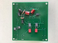
Probably you are right iggy, but I like trying things my way. Here is the first approximation, still not powered.
1) The GND plane in on the other side. Looks like I'm not alone with it - Red Baron seems to use it too. To keep the plane clean, the I2S gnd will be connected directly to pin 14 DGND. So the plane carries commons of the power supplies and the decoupling caps (50Hz DEM hopefully strongly reduces RF demands on the layout). Power supplies separate and floating - they are connected only at the GND plane.
2) Still without 12k bias resistor and 0.1u Cornell Dubilier bypasses on electrolytics. The caps are Elna Cerafine that I had at hand: 22u/50V on -5V and -15V and 100u/10V on +5V. Not sure if +5V needs that extra filtration or better -5V or all 22u...lots of choices. The black boxes are 500nH air coils.
3) For the decoupling caps I've put so far 100u/10V Elna Cerafine thinking they will do the job, they are only slightly thicker than UKA 100/25V. And only then came across the leakage current considerations. Tried to understand the issue on paper:
- John states somewhere that average pin voltages are -13V. This is contrast to the data and direct measurement reports of -7.5V max, which made me choose 10V versions as they are smaller.
- Both Elna Cerafine and UKA datasheets state the same leakage current behavior of 0.01CV, where V is the actual applied voltage. UKL are substantially less leaky.
- Looked if that 0.01 multiplier depends on the voltage itself as John suggested. By no means I am expert here, only learning, but seems that with electrolytics it stays pretty constant up to the rated voltage where it explodes exponentially. It indeed exhibit strong voltage dependence with tantalums.
Anyone with 1st hand experience on 10V DEM el-caps? May work as the paper suggests or better change to 25V straight away? John ?
1) The GND plane in on the other side. Looks like I'm not alone with it - Red Baron seems to use it too. To keep the plane clean, the I2S gnd will be connected directly to pin 14 DGND. So the plane carries commons of the power supplies and the decoupling caps (50Hz DEM hopefully strongly reduces RF demands on the layout). Power supplies separate and floating - they are connected only at the GND plane.
2) Still without 12k bias resistor and 0.1u Cornell Dubilier bypasses on electrolytics. The caps are Elna Cerafine that I had at hand: 22u/50V on -5V and -15V and 100u/10V on +5V. Not sure if +5V needs that extra filtration or better -5V or all 22u...lots of choices. The black boxes are 500nH air coils.
3) For the decoupling caps I've put so far 100u/10V Elna Cerafine thinking they will do the job, they are only slightly thicker than UKA 100/25V. And only then came across the leakage current considerations. Tried to understand the issue on paper:
- John states somewhere that average pin voltages are -13V. This is contrast to the data and direct measurement reports of -7.5V max, which made me choose 10V versions as they are smaller.
- Both Elna Cerafine and UKA datasheets state the same leakage current behavior of 0.01CV, where V is the actual applied voltage. UKL are substantially less leaky.
- Looked if that 0.01 multiplier depends on the voltage itself as John suggested. By no means I am expert here, only learning, but seems that with electrolytics it stays pretty constant up to the rated voltage where it explodes exponentially. It indeed exhibit strong voltage dependence with tantalums.
Anyone with 1st hand experience on 10V DEM el-caps? May work as the paper suggests or better change to 25V straight away? John
?Attachments
Last edited:
An important factor is to reduce the pitch between leads and make the ground lead to gnd rail the shorter you can. Just be carefull with the polarity with lytics polar caps when working with the TDA1541A.
Old std Black Gate used to perform well here. Cerafine and UKA, considering both brandnew and genuine will give you different result. Easier to find UKA as cunterfacts is probably not existing vs Elnas of all sort.
basic choice : inductance is better with short distance between radial cap leads. Here, always choose the shortest distance between leads.
You also cn consider Panasonic FC serie in your list. Lot also of small factor size in most capacitor brands.
Thank you diyiggy, but my basic question is if 10V high quality el-caps will work, main consideration being leakage current?
Inductance considerations - how much do they matter at 50Hz? I have a gnd plane on the other side of the board, thick copper - 70um to start with plus metalization so about 100um.
Cerafines - there are still good sources having them for pennies.
Inductance considerations - how much do they matter at 50Hz? I have a gnd plane on the other side of the board, thick copper - 70um to start with plus metalization so about 100um.
Cerafines - there are still good sources having them for pennies.
do they measure precisely, if he needs exactly 0.100 uf x 14 and very low leakage, inductance... better to jump on smd PPS caps...big enough in 1206 size to play with a wire instead a pcb trace...well skill trick, no itchy fingers proof Sumo.
if he talks about the dem timing cap, well i'm lost....
if he talks about the dem timing cap, well i'm lost....
I don't know if it's use the divided internal -10V of the chip or the -15V. Mainly I find there is no interest to use lytics and it's a waste here imho for this chip as I told you before. Rogic were using BG std with good sucess then went to PPS smd for some reasons I imputed. As did John as well with great precision about the layout: inductance and short conection between the caps and TDA pins : idealy direct on pins !
Lytics spec varie with time, temperature, don't age well and you need there precise capacitance and ESR. PPS smd are cheap though you may need 2% precision Panasonic or sort out PPS 20% precision if from Cornell Dublier. Both case, fragile at soldering : work fast !
That's all I can say to help on the subject... forgett also : Ceramic II & I either are not liked subjectivly there. I surmise because of internal ground share ith analog supply inside the chip but don't know really... fact it is true in real life.
Lytics are ok as supply caps, although I will not use it at last decoupling near the TDA but special cases (according regulator tipology).
hope that helps
Last edited:
- Home
- Source & Line
- Digital Line Level
- Building the ultimate NOS DAC using TDA1541A