-ecdesigns- said:Hi NjoyTHEMUSIC,
thanks for your reply [post#713],
The transformers are encapsulated torroid transformers with both very low hum and low external magnetic field. I also used them in the twin DAC. They are from Nuvotem Talema, and can be ordered at Digikey or RS components.
Yes, the resistor was placed correctly, if the motor starts spinning fast, the clock signal amplitude is too low, or the clock signal is missing. Looks like the Trichord module can't provide enough current (it's output impedance is too high, or something is wrong with the ground return path). In that case there is no choise but removing the terminating resistor like you already did. With a good clock buffer it shouldn't be a problem to drive loads as low as 50 Ohms.
cheers,
John
Hi Again John {ecdesigns}
I know you're very,very busy.
Just wanted to say "thanks" for taking the time to reply !
Best regards,
-Andy-
p.s- any family here in UK that you plan to visit with your new dac by any chance ? Heh-heh !!
-ecdesigns- said:Hi stefanobilliani,
Thanks for your reply [post#710]
> I presume you are referring to the timing chain? The shift-registers used should be fast enough to run on 11.2896 MHz, but as I previously noted, ALL DAC's that receive delayed WS and DATA must receive a inverted clock, NBCK. Only the first DAC chip that connects directly to both WS and DATA receives BCK.
> If the shift registers (timing chain) are clocked asynchronous, data corruption might occur. If the I2S reclocking circuit is clocked asynchronous, continuously varying jitter is minimized, but BCK now "jumps" between the nearest master clock transients, still the perceived sound quality is usually better than with continuously varying jitter.
> When BCK has the same frequency as the master clock this should be possible. If I am correct, dividing BCK can cause loss of synchronization.
Hello ecdesigns ,
Thanks for your reply (post 720)
Yes I was referring to the timing chain.
Based on your circuit and recent observations regarding the BCK for the DACS involved on the timing chain I builded a test set up with 4 TDA1543 .
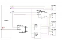
Attacched is the block diagram concept actually builded .
It refears to a pratical-building possibility looking at the matter of buffers and inverter .
It uses a 74HC74 (or even better 74VHC74)dual flip flop that acts as buffer / reclocker and inverter .
74HC74 buffers / reclock BCK at the output of the spdf receiver . Using this scheme all the lines outputs of the CS8412 ( and of course it would be the same for a I2S line from a CD player ) are driving just 2 input gates . The 2 Flip Flop are clocked at 11.2896 Mhz by the MCK output (pin n°19) of the CS8412 .
One of the 2 Flip Flops deliver both BCK for dac 1 and the Inverted BCK to DAC n° 2 .... 4 in this example .
The other F F acts "just" like a buffer for the complete timing chain .
Attachments
hi all,
I had a small idea, hope to know how many diyers will had interest.
Since john's pay most effort's Ultimate 1541aDAC design need more chips. ( TDA1541A).
I received some emails ask for more pcs of 1541a & 1543.
So I hope to prepare a groups buy for the chips.
I need to groups more order & will match ordered chips in same date code from me.
It means now I prepare order chips will
TDA1541a--- I still had 150 pcs on hand, but not easy to match same date code for 8 pcs or more.
TDA1543--- dealer had 1000pcs on stock.
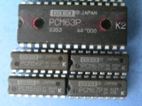
PCM56( made in japan). ---- I order 1000pcs already. for my coming design 32Pcs of PCM56 DAC.
TDA1541a will USD10 per one.
TDA1543will USD1.5 per one.
All include IC sockets.
CS-8414 & 8412-IS include adapter will USD 10 per one.
PCM56 had made in japan & made in korea. By the report of Audionote japan.Japan made chips will better than Korea. Looks long times ago Kondo had one design was use PCM56 for NOS DAC, I am not sure, I need to check.
Pls let me know an diyers had interest.john paid more more effort design in his DAC than me. I hoe my little power can support more member in this diyaudio.comcan enjoy best product which was design by diyers & will not same as standard factory products will considerate earn more money, profit was the first priority of their products.
hope this can help.
All price include postage & paypal charge already.
But pls not onl order one or two chips, I will lost money in paypal charge.
Pls more questions, pls refer ack into my thread. I not like to disturb john's techanical discuss in here.
thx
thomas
I had a small idea, hope to know how many diyers will had interest.
Since john's pay most effort's Ultimate 1541aDAC design need more chips. ( TDA1541A).
I received some emails ask for more pcs of 1541a & 1543.
So I hope to prepare a groups buy for the chips.
I need to groups more order & will match ordered chips in same date code from me.
It means now I prepare order chips will
TDA1541a--- I still had 150 pcs on hand, but not easy to match same date code for 8 pcs or more.
TDA1543--- dealer had 1000pcs on stock.
PCM56( made in japan). ---- I order 1000pcs already. for my coming design 32Pcs of PCM56 DAC.
TDA1541a will USD10 per one.
TDA1543will USD1.5 per one.
All include IC sockets.
CS-8414 & 8412-IS include adapter will USD 10 per one.
PCM56 had made in japan & made in korea. By the report of Audionote japan.Japan made chips will better than Korea. Looks long times ago Kondo had one design was use PCM56 for NOS DAC, I am not sure, I need to check.
Pls let me know an diyers had interest.john paid more more effort design in his DAC than me. I hoe my little power can support more member in this diyaudio.comcan enjoy best product which was design by diyers & will not same as standard factory products will considerate earn more money, profit was the first priority of their products.
hope this can help.
All price include postage & paypal charge already.
But pls not onl order one or two chips, I will lost money in paypal charge.
Pls more questions, pls refer ack into my thread. I not like to disturb john's techanical discuss in here.
thx
thomas
Attachments
Hi all,
This maybe unrelated but since I am using the tda1541 as well, here is my way to improve the dac: use harddisk as transport and skip the cs8414 and go I2S directly.
I use a 160G HD media player (just a card with video and harddisk interface) and tap the I2S from the DSP to the TDA1541. I think this is a relatively low cost and easy way to avoid the jitter problem caused by SPIF.
http://www.diyaudio.com/forums/showthread.php?s=&threadid=84056
Now if I can replace the single 1541 with ecdesigns setup, that would be a killer.
Octal D-I DAC connects to the mac
Hi all,
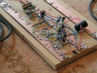
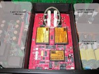
Well, I build a USB to I2S prototype setup and tested it for two days. I added a photograph of the prototype setup.
As already noted, I used the PCM2706. So how did it perform? as I already expected, BCK shows a abundance of jitter and the soundstage collapsed. And this was with a clean 3.3V external power supply, so first thing I tried was a very short USB cable, no, still lot's of jitter. Then I measured the 12 MHz clock signal, not a pretty sight, so I replaced it by a stable external 12 MHz oscillator. Still the jitter persisted. So I stuck with a bad jittery BCK.
Next attempt, synchronous reclocking. I opened my imac and compared all available clock's with BCK, unfortunately non of them was in sync. Next option then, asynchronous reclocking.
First I tried classic asynchronous reclocking at 40 MHz with two D-flipflops, and believe it or not, but the sound quality improved significantly. The soundstage started to open up, and bass was more accurate, but I wanted best possible performance.
After many test setup's I stumbled across a very peculiar reclocking setup, call it semi-asynchronous reclocking. My idea was to remove one of both crystal oscillators since these two separate oscillators (40MHz and 12 MHz) don't run in sync. The PCM2706 needs 12 MHZ, and reclocking needs at least 40 MHz.
So why not use a 48 MHz reclock frequency and divide it by 4 to get the 12 MHz for the PCM2706, this way both signals run in sync. When I switched-on again sound quality was very impressive, the oscillogram showed a strange BCK signal. Besides the absence of the noisy jitter, the positive going edge of BCK seemed to have only one transient (this is where the TDA1541A sync's), the trailing edge showed the dual transient as is normal with asynchronous reclocking. So basically the critical positive going edge of BCK looked much better now.
Then lot's of people say a USB interface must have a external power supply because the USB power supply is so noisy. Well it contains some minor interference that can easily be filtered out. So I tried it anyhow, I used the USB power supply for the USB to I2S interface, but I tricked the PCM2706. I put the PCM2706 in self powered mode, added a high quality external 3.3V regulator....and connected it to the USB power supply. It worked very well, sound quality now is comparable with my reference CD changer. Oh yes, I also added differential I2S output. And cable length? surprise, this USB to I2S converter can have 10m of USB cable and about 2.5m of differential I2S cable. So the computer can be placed about 12.5m from the DAC, not bad.
So now a tiny USB / I2S interface can be constructed that is powered by the USB socket and connects directly to the octal D-I DAC I2S input. By adding a mac with Itunes we have a High-End sound machine with thousand's of songs at the push of a button, in high-quality lossless format that is. There is even a equalizer integrated in Itunes. Worried of backing-up the many sound files in case of a HD crash, Apple comes to the rescue with the amazing Leopard operating system. Among dazzling 3D effect's, this new operating system also includes "Time Machine", a uniquely integrated real-time back-up system using a external HD. This way your sound files are as safe as can be.
Hi all,
Well, I build a USB to I2S prototype setup and tested it for two days. I added a photograph of the prototype setup.
As already noted, I used the PCM2706. So how did it perform? as I already expected, BCK shows a abundance of jitter and the soundstage collapsed. And this was with a clean 3.3V external power supply, so first thing I tried was a very short USB cable, no, still lot's of jitter. Then I measured the 12 MHz clock signal, not a pretty sight, so I replaced it by a stable external 12 MHz oscillator. Still the jitter persisted. So I stuck with a bad jittery BCK.
Next attempt, synchronous reclocking. I opened my imac and compared all available clock's with BCK, unfortunately non of them was in sync. Next option then, asynchronous reclocking.
First I tried classic asynchronous reclocking at 40 MHz with two D-flipflops, and believe it or not, but the sound quality improved significantly. The soundstage started to open up, and bass was more accurate, but I wanted best possible performance.
After many test setup's I stumbled across a very peculiar reclocking setup, call it semi-asynchronous reclocking. My idea was to remove one of both crystal oscillators since these two separate oscillators (40MHz and 12 MHz) don't run in sync. The PCM2706 needs 12 MHZ, and reclocking needs at least 40 MHz.
So why not use a 48 MHz reclock frequency and divide it by 4 to get the 12 MHz for the PCM2706, this way both signals run in sync. When I switched-on again sound quality was very impressive, the oscillogram showed a strange BCK signal. Besides the absence of the noisy jitter, the positive going edge of BCK seemed to have only one transient (this is where the TDA1541A sync's), the trailing edge showed the dual transient as is normal with asynchronous reclocking. So basically the critical positive going edge of BCK looked much better now.
Then lot's of people say a USB interface must have a external power supply because the USB power supply is so noisy. Well it contains some minor interference that can easily be filtered out. So I tried it anyhow, I used the USB power supply for the USB to I2S interface, but I tricked the PCM2706. I put the PCM2706 in self powered mode, added a high quality external 3.3V regulator....and connected it to the USB power supply. It worked very well, sound quality now is comparable with my reference CD changer. Oh yes, I also added differential I2S output. And cable length? surprise, this USB to I2S converter can have 10m of USB cable and about 2.5m of differential I2S cable. So the computer can be placed about 12.5m from the DAC, not bad.
So now a tiny USB / I2S interface can be constructed that is powered by the USB socket and connects directly to the octal D-I DAC I2S input. By adding a mac with Itunes we have a High-End sound machine with thousand's of songs at the push of a button, in high-quality lossless format that is. There is even a equalizer integrated in Itunes. Worried of backing-up the many sound files in case of a HD crash, Apple comes to the rescue with the amazing Leopard operating system. Among dazzling 3D effect's, this new operating system also includes "Time Machine", a uniquely integrated real-time back-up system using a external HD. This way your sound files are as safe as can be.
Attachments
USB jitter
Hi all,
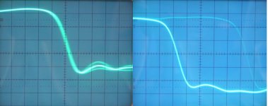
I added a oscillogram from the "USB" BCK signal. The left oscillogram shows BCK jitter that appears as a haze along both the leading and trailing edge of BCK. This jitter value is totally unacceptable. Right oscillogram shows the semi-asynchronous reclocked BCK signal, jitter is greatly reduced, and best of all, the asynchronous reclocking side-effect's now concentrate on the trailing edge of BCK.
Hi all,
I added a oscillogram from the "USB" BCK signal. The left oscillogram shows BCK jitter that appears as a haze along both the leading and trailing edge of BCK. This jitter value is totally unacceptable. Right oscillogram shows the semi-asynchronous reclocked BCK signal, jitter is greatly reduced, and best of all, the asynchronous reclocking side-effect's now concentrate on the trailing edge of BCK.
Attachments
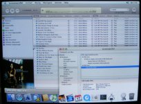
imac Itunes screenshot
Hi all,
I added a photograph of the "High-End sound machine" interface") , It's a imac screenshot. Need to find a song? just type some text, in this example I wanted to play some songs of Katie Melua. So I just type katie, and all songs appear, with a photograph of the CD cover included. It's quite impressive to just click on the track you want to listen too, and it is immediately played back in High-End sound quality. The songs are stored on a 160Gb HD using lossless compression (about half the size of a CD image). Oh yes, this old imac needs no fan, so it's whisper silent.
, It's a imac screenshot. Need to find a song? just type some text, in this example I wanted to play some songs of Katie Melua. So I just type katie, and all songs appear, with a photograph of the CD cover included. It's quite impressive to just click on the track you want to listen too, and it is immediately played back in High-End sound quality. The songs are stored on a 160Gb HD using lossless compression (about half the size of a CD image). Oh yes, this old imac needs no fan, so it's whisper silent.
Hi all,
I added a photograph of the "High-End sound machine" interface
, It's a imac screenshot. Need to find a song? just type some text, in this example I wanted to play some songs of Katie Melua. So I just type katie, and all songs appear, with a photograph of the CD cover included. It's quite impressive to just click on the track you want to listen too, and it is immediately played back in High-End sound quality. The songs are stored on a 160Gb HD using lossless compression (about half the size of a CD image). Oh yes, this old imac needs no fan, so it's whisper silent.Attachments
Re: Octal D-I DAC connects to the mac
Congratulations on your success. Sounds like the job satisfaction level was quite high there.
I'd just like to mention that you can use Audio Hijack Pro to use a nice digital AU or VST equalizer plugin after iTunes. There isn't anything particularly wrong with the iTunes EQ, and I use it, but I've heard "proper" EQ plugins that I somehow enjoyed more.
There's some very nice freeware N-band EQs out there, and good freeware parametric EQs can probably be found. There's also very nice paid-for EQs. If you happened to have a Waves bundle, that ought to be fun. Also, the Kjaerhus EQ plugins are probably nicest-sounding ones that I've used. (I'm no expert though, I just enjoyed their sound.)
Again, congrats, and thanks for sharing. Just felt the need to post some thoughts.
Congratulations on your success. Sounds like the job satisfaction level was quite high there.
-ecdesigns- said:By adding a mac with Itunes we have a High-End sound machine with thousand's of songs at the push of a button, in high-quality lossless format that is. There is even a equalizer integrated in Itunes.[/B]
I'd just like to mention that you can use Audio Hijack Pro to use a nice digital AU or VST equalizer plugin after iTunes. There isn't anything particularly wrong with the iTunes EQ, and I use it, but I've heard "proper" EQ plugins that I somehow enjoyed more.
There's some very nice freeware N-band EQs out there, and good freeware parametric EQs can probably be found. There's also very nice paid-for EQs. If you happened to have a Waves bundle, that ought to be fun. Also, the Kjaerhus EQ plugins are probably nicest-sounding ones that I've used. (I'm no expert though, I just enjoyed their sound.)
Again, congrats, and thanks for sharing. Just felt the need to post some thoughts.
Re: USB jitter
I'm sure everybody here knows that, by definition, asynchronous reclocking creates jitter with a guaranteed peak to peak time greater than the period of the asynch clock.
-ecdesigns- said:Right oscillogram shows the semi-asynchronous reclocked BCK signal, jitter is greatly reduced, and best of all, the asynchronous reclocking side-effect's now concentrate on the trailing edge of BCK.
I'm sure everybody here knows that, by definition, asynchronous reclocking creates jitter with a guaranteed peak to peak time greater than the period of the asynch clock.
Jitter shape and amplitude
Hi Ulas,
Thanks for your reply [post#731]
Yes asynchronous reclocking creates jitter as can be seen on the posted oscillograms, but this jitter creates phase shifts between two fixed positions. Listening sessions have clearly indicated that continuous jitter (appears as a haze as can be seen on the left oscillogram) has a bad effect on sound quality, even with much lower jitter amplitudes. Kusonoki has published similar findings.
I also checked this many times, if sound quality isn't optimal it's almost certain to see a slight haze on the BCK transients.
So basically when phase only jumps between two fixed positions (crystal clock transients), perceived sound quality is much better than with a much lower amplitude continuous jitter. So the shape of the jitter signal appears to be even more important than it's amplitude.
The reclocking circuit I have used in the USB interface, is synchronized with the PCM2706 clock. Reclocking is now done on both positive and negative going edges of the 48MHz clock. By using this setup, reclock jitter is mainly concentrated on the trailing edge. Since the TDA1541A uses the leading edge to sync, this setup gives exeptionally good results. I just had to add isolation transformers in the differential interface because the switched mode power supply of some computers caused interference on BCK. After adding the transformers, interference was gone and sound quality improved.
I just compared both setups (the CD changer with direct I2S sony format and the PCM2706 USB interface) this is possible now since the new timing chain automatically detects sony or philips format and adjusts both format converter and timing-chain taps accordingly. I used familiar music, so I knew exactly what to listen for. Even when listening very critically it's difficult to keep them apart. When the USB reclocking is disabled, the difference between direct I2S and the USB interface is clearly audible.
The USB to I2S interface has jitter, lot's of it. It can be reduced a little bit by (drastic) measures, but it's still way to high for continuous jitter. There is no (crystal) clock signal available that run's in sync with BCK, in order to apply synchronous reclocking. So this asynchronous reclocking setup, using a single 48MHz crystal clock for both reclocking and PCM2706 clock seems to be a good alternative to obtain optimal sound quality.
Ecdesigns, I have a Cambridge cd player (15 years old) with 16x over sampling, and the design of the dac is very similar to your design, 4 TDA1541A and 6 sn74ls166 for the delay line. They only use 3 sn74ls166 for data and 3 for ws, in the datasheet of the saa7220 the output data is 32bit wide, the first dac is connected direct from 7220, the 2º is delay 8 bit, the 3º delay 16 bit and 4ºdac is delay 24bit. A year ago I have bypassed the sa7220 and connected direct to the saa7210 output, but I don’t now if the output of the saa7210 is 32bit wide.
The sound have improved in some cd´s , but now I have it connected as before, I am designing a class b, low high frequency distortion, no feedback amp to use with this type of dac (not easy, but is almost finish). My doubt is why your design use 64bit wide? Is the output of the saa7210 a 32bit wide?
Sorry for the silly questions but I only start reading your thread yesterday and my strong is power amps (analog).
Ps: These 2 questions are for every one of the forum, thanks… and sorry for my English.
Re: Jitter shape and amplitude
You’re not looking at clock jitter with your scope. What you are seeing is pulse width jitter, which is irrelevant. It looks like you are triggering the scope on the rising edge of BLCK, so of course you’re not going to see jitter on the rising edge. Unfortunately, that’s the only edge that matters. To see jitter on a scope you need a stable time reference that is synchronous with the sample rate. Probably the best you can do is trigger on WCLK and look at the rising edge of the second following BCLK; that’s when the TDA1541A changes the state of the analog output. To do that with an analog scope you’ll need one with a delayed trigger. The alternative is to use a spectrum analyzer and something like Julian Dunn’s jitter test signal.
You guys make me laugh. On one hand, you say small amounts of jitter are bad and take extreme measures to reduce it but, on the other hand, you say large amounts of jitter are good; it just depends on the frequency distribution. That’s like saying a recording with a small amount of tape hiss is bad but a recording with a large amount of tape hiss is good provided the hiss has the right frequency spectrum. How can that be? To accurately reproduce digital audio, the D/A clock must exactly match the A/D clock. Any deviation, whatever the frequency, distribution, or other characteristic, constitutes jitter, which is, or should be, undesirable.
The CS841x outputs a new sample every 1/44100 seconds. That’s one sample every 22675.73696 ns. If the first sample comes at time 0ns, the second sample will come at time 22675.74ns, the third at time 45351.47ns, the fourth at time 68027.21ns, etc. Oh, there may be as much as 200ps RMS jitter and that’s VERY BAD.
Adding a 48MHz asynchronous reclocker simply delays each sample-time to the next multiple of 20.8333ns, which means every sample will be between 0 and 20.8333ns late. That’s assuming an ideal latch. In the real world, 48MHz reclocking will create about 12ns RMS jitter. The time period between successive BCLKs will essentially alternate between 22,687.50ns and 22,666.67ns. Now, that’s what I call JITTER and, apparently, you think that’s a good thing.
Can you explain the characteristics of jitter that make it desirable? If you can do that, why don’t you make a circuit that takes a perfectly good digital audio signal with little or no jitter, and adds just the right amount of the right kind of jitter to make the music come to life. If you did that and patented the idea you could make a fortune. A dedicated circuit to add just enough jitter is certainly better then hit and miss efforts with different reclocking schemes and would certainly be better than the wasted efforts audiophiles go through to reduce jitter.
Would you please explain why the DAC sample clock needs to synchronized with the 12MHz USB clock? The purpose of the 12MHz clock is to clock data to and from the USB bus. It has absolutely nothing to with the function of the DAC. Look at any USB device and you will see a 12MHz crystal.
The sample rate of a USB DAC is determined exclusively by the rate at which the host sends samples. Every millisecond the host sends a packet containing a millisecond’s worth of samples. When the sample rate is 44.1KHz, not every packet contains the same number of samples. It is up to the DAC to distribute the samples evenly across the next millisecond. Some USB DACs literally distribute the samples across one millisecond and have what could best be described as 3% wow and flutter as the sample frequency changes every few milliseconds. Others attempt to even out the distribution across a longer time span. That, and the fact the sample clock is the output of a VCO, unrelated to the 12MHz crystal, means all USB DACs have large amounts of jitter, which, according to you, is a good thing. Or maybe I have that backwards. Oh yeah, other diyAudio Experts claim USB digital audio has NO jitter, which is also supposed to be a good thing. So which is better, no jitter or lots of jitter?
-ecdesigns- said:Yes asynchronous reclocking creates jitter as can be seen on the posted oscillograms, but this jitter creates phase shifts between two fixed positions.
You’re not looking at clock jitter with your scope. What you are seeing is pulse width jitter, which is irrelevant. It looks like you are triggering the scope on the rising edge of BLCK, so of course you’re not going to see jitter on the rising edge. Unfortunately, that’s the only edge that matters. To see jitter on a scope you need a stable time reference that is synchronous with the sample rate. Probably the best you can do is trigger on WCLK and look at the rising edge of the second following BCLK; that’s when the TDA1541A changes the state of the analog output. To do that with an analog scope you’ll need one with a delayed trigger. The alternative is to use a spectrum analyzer and something like Julian Dunn’s jitter test signal.
You guys make me laugh. On one hand, you say small amounts of jitter are bad and take extreme measures to reduce it but, on the other hand, you say large amounts of jitter are good; it just depends on the frequency distribution. That’s like saying a recording with a small amount of tape hiss is bad but a recording with a large amount of tape hiss is good provided the hiss has the right frequency spectrum. How can that be? To accurately reproduce digital audio, the D/A clock must exactly match the A/D clock. Any deviation, whatever the frequency, distribution, or other characteristic, constitutes jitter, which is, or should be, undesirable.
The CS841x outputs a new sample every 1/44100 seconds. That’s one sample every 22675.73696 ns. If the first sample comes at time 0ns, the second sample will come at time 22675.74ns, the third at time 45351.47ns, the fourth at time 68027.21ns, etc. Oh, there may be as much as 200ps RMS jitter and that’s VERY BAD.
Adding a 48MHz asynchronous reclocker simply delays each sample-time to the next multiple of 20.8333ns, which means every sample will be between 0 and 20.8333ns late. That’s assuming an ideal latch. In the real world, 48MHz reclocking will create about 12ns RMS jitter. The time period between successive BCLKs will essentially alternate between 22,687.50ns and 22,666.67ns. Now, that’s what I call JITTER and, apparently, you think that’s a good thing.
Can you explain the characteristics of jitter that make it desirable? If you can do that, why don’t you make a circuit that takes a perfectly good digital audio signal with little or no jitter, and adds just the right amount of the right kind of jitter to make the music come to life. If you did that and patented the idea you could make a fortune. A dedicated circuit to add just enough jitter is certainly better then hit and miss efforts with different reclocking schemes and would certainly be better than the wasted efforts audiophiles go through to reduce jitter.
Would you please explain why the DAC sample clock needs to synchronized with the 12MHz USB clock? The purpose of the 12MHz clock is to clock data to and from the USB bus. It has absolutely nothing to with the function of the DAC. Look at any USB device and you will see a 12MHz crystal.
The sample rate of a USB DAC is determined exclusively by the rate at which the host sends samples. Every millisecond the host sends a packet containing a millisecond’s worth of samples. When the sample rate is 44.1KHz, not every packet contains the same number of samples. It is up to the DAC to distribute the samples evenly across the next millisecond. Some USB DACs literally distribute the samples across one millisecond and have what could best be described as 3% wow and flutter as the sample frequency changes every few milliseconds. Others attempt to even out the distribution across a longer time span. That, and the fact the sample clock is the output of a VCO, unrelated to the 12MHz crystal, means all USB DACs have large amounts of jitter, which, according to you, is a good thing. Or maybe I have that backwards. Oh yeah, other diyAudio Experts claim USB digital audio has NO jitter, which is also supposed to be a good thing. So which is better, no jitter or lots of jitter?
hi MGH,
mike, pls email to yor post address to me again. For the 8 ps of 1541a . I would like to post 8chips to u to test for john's ultimate design.
Mike, My ver.3 dac ( in my view is ultimate but less than john's design) can use CM106L & PCM2906.
PCM2702, 2706 not good, if u play cd fro the computor use 2702,2706,2906 interface change to spdif.
2906 will be best, the best sound qualty that i found in my test.
Since PCM2906 & etc all were USB 1.1 I U like to use DVD audio or other format which need higher band width. CM106L will be beter because it had USB2.0. I prepare two module for this two chips. So diyers use my dac can interchange two module for running two formats.
BTW,
I need your address.
pls send to
thomas_siu@hotmail.com
thx
thomas
hi Mike, the
ultimate V.3 can running in single or parallel 1541a. U can choose or plug one more PCB to parallel running.
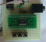
May be U will had interest to take a look for the PCM2906 USB receiver module. THis is my hand made for test only.
thx
thomas
ultimate V.3 can running in single or parallel 1541a. U can choose or plug one more PCB to parallel running.
May be U will had interest to take a look for the PCM2906 USB receiver module. THis is my hand made for test only.
thx
thomas
Attachments
- Home
- Source & Line
- Digital Line Level
- Building the ultimate NOS DAC using TDA1541A