I have used the following sampl.freq: 40960, 44100, 48000,96000I will do the same sim, but now with 44.1/16.
Noise floor is dependant on the filter bin width, when you give me the length of the FFT and the sample rate you used, I will use these same figures.
Let's see how this works out.
Hans
And FFT samples: 4096, 22050, 32768, 65536
And I use Hanning smoothing.
No big changes between, besides the expected: low sampling freq and many samples results in shallower peaks. And with many samples the noise floor is around -115dB
And of course changes in spuriouses...
I changed my input soundcard to a Behringer UCA222. It has a little bit higher noise floor, but no spurious.I will do the same sim, but now with 44.1/16.
Noise floor is dependant on the filter bin width, when you give me the length of the FFT and the sample rate you used, I will use these same figures.
Let's see how this works out.
Hans
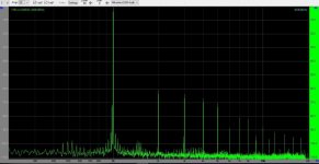
The two pics are FS and FS -6dB.
Signed Magnitude TDA1541A with 75 Ohm I/V resistor and about 1K45 to +6,28V Vcc.
Attachments
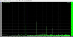
Please compare it with the FFT graph of a standard implementation
TDA1541A board from a Philips CD player
TDA1541A board from a Philips CD player
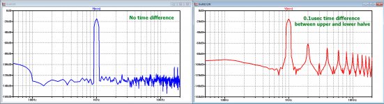
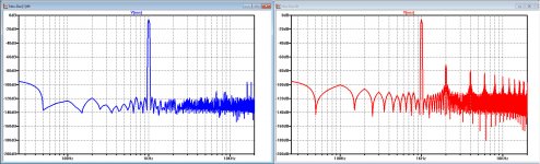
Here is the effect of a time shift between the upper and the lower halve after sampling and digitizing 44.1kHz/17.
Images below: left no time difference, right a 0.1usec shift.
Effect of such a small time shift is already quite dramatic as can be seen.
I used a time window of 20msec, giving 50Hz bins from the FFT.
Using a larger time window, will let the noise drop by the sqrt of the time window and make the "feet" of the harmonics much smaller.
Hans
Attachments
The two pics are FS and FS -6dB.
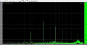
Not a very good spectrum, there is work to do. Here for comparison the spectrum of my DAC. The DAC includes a single TDA1541A chip and an I/U converter on an operational amplifier (feedback resistance R=1k8).
Attachments
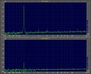
I extended the time window for simulation from 20m to 40msec, now showing more detail and I also corrected a small inaccuracy.
Now again the spectrum without time shift left, and for a time shift of 0.2usec at the right, taken with a 1kHz -6dB signal.
It corresponds remarkebly good with Koldbys -6dB spectrum in #7202.
Hans
Now again the spectrum without time shift left, and for a time shift of 0.2usec at the right, taken with a 1kHz -6dB signal.
It corresponds remarkebly good with Koldbys -6dB spectrum in #7202.
Hans
Attachments
Last edited:
Yes this could be the reason for this even order harmonic pattern. If it is an internal timing difference, then perhaps it is better to use the same side (right - left) DAC in two different TDA1541A , so you use one TDA1451A for the two positive halves (right and left) and the other TDA1541A for two negative halves (right and left)?I extended the time window for simulation from 20m to 40msec, now showing more detail and I also corrected a small inaccuracy.
Now again the spectrum without time shift left, and for a time shift of 0.2usec at the right, taken with a 1kHz -6dB signal.
It corresponds remarkebly good with Koldbys -6dB spectrum in #7202.
Hans
On another note. Like weissi say , this could actually be a spectrum from a DAC that sounded really good. The precense of only even order harmonics and the very linear decay of higher order harmonics is much what the air does to sound preassure. I am not at all sure that the spectrum SSerg is showing, would result in a better sound.
Data Right is delayed 0,2 Usec vs Data Left because Data R goes through the 'Control & Timing' circuit that Data L doesn't at the input of TDA1541A.
But shouldn't the conversion of the numbers (data) stored in the registers be transferred to the current sources at the transition of LE at exactly the same time in both right and left channel??
I am not at all sure that the spectrum SSerg is showing, would result in a better sound.
The sound is very good. And this is not surprising. Given the simplicity and conciseness of the scheme, there are good prerequisites for good sound.
The sound is very good. And this is not surprising. Given the simplicity and conciseness of the scheme, there are good prerequisites for good sound.
I am sure it sounds very good, but I am not sure, just judging from the spectrum's, that it would sound any better than what I am measuring.
I am sure it sounds very good, but I am not sure, just judging from the spectrum's, that it would sound any better than what I am measuring.
OK
Agreed. I also have great results with 6c33c based OTL. Another win was using autoformer volume control replacing any kind of resistor based attenuation. Sounds like I need to try sample transformer I/V..
Max. Would be interesting to hear results of your experiments with Thyratron rectifiers.
It's only a wish. I know nothing about the practical use of Thyratron (nor about tubes) but they are sooo cool!
 Plasma heaven.
Maybe now that there are no kids around
 I could experiment with tubes.
On the other side, VFETs have triode behavior and could last forever.
About TXs I read that "Living Stereo" recordings were made with transformer based electronics, Tx based mic preamp perhaps? They sound good even for its age. The Master tapes should sound fantastic. In that era the recording engineers would not dare to compress the dynamics
Cheers,
M.
In my DAC, I use tube rectifiers for the tube output stage. Works fine and not hard to wire point to point. Surprising difference in sound by tube rolling just the rectifiers btw.
But I never thought about tube rectifiers for the digital PS. I did start with ordinary rectifiers and then upgraded to supersoft recovery. As most report, the sound improvement was significant. So it begs the question if tube rectifiers would be a fine choice here as well. Certainly looks cool.
But I never thought about tube rectifiers for the digital PS. I did start with ordinary rectifiers and then upgraded to supersoft recovery. As most report, the sound improvement was significant. So it begs the question if tube rectifiers would be a fine choice here as well. Certainly looks cool.
If you're using valves...it doesn't matter what dac is in front of it...
That was a strange comment. Have you ever tried it?
I guess not.
I extended the time window for simulation from 20m to 40msec, now showing more detail and I also corrected a small inaccuracy.
Now again the spectrum without time shift left, and for a time shift of 0.2usec at the right, taken with a 1kHz -6dB signal.
It corresponds remarkebly good with Koldbys -6dB spectrum in #7202.
Hans
Hi Hans
Your simulation and my measurements along with Phillips data on TDA1541A seemed to point at a time difference between the two dac's inside the TDA1541A.
The strange thing is , that Phillips has no values for typ. and min. for the time difference between the two channels, only max. (0,2 us) . That could lead one to the conclusion , that there always was this timing difference between the channels, supported by the fact that the spectrum I measure is the same even if I switch the TDA1541A I am measuring.
So I thought to myself , if there is a consistent time difference between R and L dac, this problem could be solved by using two R dac's to convert the two halves of the R channel and two left dac's to convert the two halves of the left channel.
So I switched the DATA in so one TDA1541A recieved DOL+ and DOR+ and the other TDA1541A DOL- and DOR- . Then I took the I out from the two TDA1541A's R channels and combined them and the same for the two L channels.
Bingo that worked!
Unfortunately, the result is quite unconclusive, as the spectrum is almost identical to the FS -6dB , when using one TDA1541A to convert both halves. It is in fact a little worse, but still only even order harmonics.
What could be the next step?
Attachments
In this latest configuration, as I see it, it would be possible to verify if it indeed was a timing difference that produced that spectrum, by inserting a variable time delay in the LE to one of the TDA1541A and then watch what happens when this time delay is varied.
Is it possible to make such a variable time delay easily?
Perhaps it would be easiest to insert a known non variable timedelay to the other TDA1541A so the timing between the to could go from + delay to - delay?
Is it possible to make such a variable time delay easily?
Perhaps it would be easiest to insert a known non variable timedelay to the other TDA1541A so the timing between the to could go from + delay to - delay?
- Home
- Source & Line
- Digital Line Level
- Building the ultimate NOS DAC using TDA1541A