Someone did something similar a while ago in order to create a fast enough data rate to allow the use of the external digital filter interface of the PCM1792, bypassing the internal digital filter and with some success it would seem.
Must say from a purely technical viewpoint without the extra samples created an FIR oversampling filter or something similar, there is likely to be a degree of error in the HF area due to a lack of samples though there now appears to be at least two cases that suggest this may not be a problem.
As for the title Ultimate, I'd have to take issue with that, not least because it uses the TDA1541A, but mainly because the Japanese audio crazies build these things with 64 dacs per channel, with or without a preceeding OS filter.
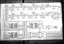
Twin DAC diagram
Hi,
I try to post the Twindac diagram but couldn't get the file small enough. I will give it another try (This DAC uses the 8th order active filter and differential stage).
About the Direct Interpolation questions, there is one major difference with existing methods. Brickwall filtering is necessary to filter out the noise introduced during oversampling / digital filtering. The Direct Interpolation DAC uses no oversampling, no decimation and no digital filtering, so there is no need for a brickwall filter. Yes the output signal of the Direct Interpolation DAC still has steps, but these are 4 times the ANALOG resolution (18 bits). Because the virtual sample rate is now 176.4KHz a standard 2nd order EXTERNAL filter is sufficient, just like in the standard designs that do use oversampling and digital interpolation filters. And remember, the prototype is working perfectly without interference, the output signal is very clean and has no steps after the 2nd order Bessel filter, so this is not just a theory.
Attachments
Re: SPDIF (white connector)
I have no doubt the 8412 is much happier with your interface. Still, one may question how well the 110 ohm terminates the mixture of cables and connectors.
Your mixed signal interpolation idea appears interesting and elegant to me but the chain of 5 opamps seems absolutely frightful and against the NOS minimalism.
-ecdesigns- said:Hi analog sa,
The white connector you referred to is actually the analog output. I use a custom made fully differential SPDIF interface like in professional sound studio equipment. So no 75 OHm coax cable, certainly no TOSlink, actually I am using standard SVHS cable for this purpose. So I have a normal and an inverted SPDIF signal to cancel out interference that causes jitter. Obviously I had to modify my CD player
I have no doubt the 8412 is much happier with your interface. Still, one may question how well the 110 ohm terminates the mixture of cables and connectors.
Your mixed signal interpolation idea appears interesting and elegant to me but the chain of 5 opamps seems absolutely frightful and against the NOS minimalism.
Some information about Direct Interpolation
Hi all,
Here some information about the Direct Interpolation DAC.
Twin Direct Interpolation by parallelling DAC outputs:
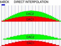
It uses the WS signal to split up the 64 BCK pulses long sample into two 32 BCK long samples DAC1 receives the standard signals and outputs L and R. DAC2 receives an inverted WS (wordselect) causing a 32 BCK long delay (WS determines when the sample appears at the DAC output). This all creates 2 samples of 32 BCK pulses each: 1-32, 32-64. so the virtual sample rate becomes 44.1 * 2 = 88.2 KHz. This can be verified by observing the output signal with an oscilloscope. Because all analog outputs are ADDED, the following intermediate steps are created:
1-32 (DAC1)
32-64(DAC1+DAC2)
These addittional steps increase the output resolution to (2*65536=131072) equivalent to 17 bit resolution as DAC output voltages are added stepwise.
Here is an overview of how to connect each of the 2 DAC's
DATA DAC1 = DATA
BCK DAC1 = BCK
WS DAC1 = WS
L OUT = L OUT
R OUT = R OUT
DATA DAC2 = DATA
BCK DAC2 = BCK
WS DAC2 = NWS (inverted)
L OUT = R OUT (swapped)
R OUT = L OUT (swapped)
So basically if you already have a twin DAC and you want to try this, just invert WS on the second DAC and swap its L and R outputs. You will get 88.2KHz virtual sample rate and 17 bits. If you like a differential output stage, invert DATA of DAC2: NDATA
Quad Direct Interpolation using differential output stage
It uses the WS signal to split up the 64 BCK pulses long sample into two 32 BCK long samples then a 16 BCK delay (two sets of 2 * SN74HCT166 cascaded, one for DATA the other for WS) is applied to both DATA and WS of DAC 3. DAC4 gets the same treatment as DAC2 plus an addittional 16 BCK pulses so 48 BCK pulses delay. This all creates 4 samples of 16 BCK pulses each: 1-16, 16-32, 32-48, 48-64. so the virtual sample rate becomes 44.1 * 4 = 176.4 KHz. This can be verified by observing the output signal with an oscilloscope.
Because all analog outputs are ADDED, the following
intermediate steps are created:
1-16 (DAC1)
16-32(DAC1+DAC2)
32-48(DAC1+DAC2+DAC3)
48-64(DAC1+DAC2+DAC3+DAC4)
These addittional steps increase the output resolution to (4*65536=262144) equivalent to 18 bit resolution as DAC output voltages are added stepwise.
Here is an overview of how to connect each of the 4 DAC's
DATA DAC1 = DATA
BCK DAC1 = BCK
WS DAC1 = WS
L OUT = L OUT
R OUT = R OUT
DATA DAC2 = NDATA (inverted) causes 32 BCK pulses delay but swaps outputs
BCK DAC2 = BCK
WS DAC2 = NWS (inverted), causes 32 BCK pulses delay
L OUT = NR OUT (swapped, inverted)
R OUT = NL OUT (swapped, inverted)
DATA DAC3 = DLY16CP DATA (delayed 16 BCK pulses using 74HCT166 shift register)
BCK DAC3 = BCK
WS DAC3 = DLY16CP WS (delayed 16 BCK pulses using 74HCT166 shift register)
L OUT = L OUT (parallel to DAC1)
R OUT = R OUT (parallel to DAC1)
DATA DAC4 = NDATA DLY48 (inverted)causes 48 BCK pulses delay but swaps outputs
BCK DAC4 = BCK
WS DAC4 = NWS (inverted)
L OUT = NR OUT (swapped, inverted, parallel to DAC2)
R OUT = NL OUT (swapped, inverted, parallel to DAC2)
Hi all,
Here some information about the Direct Interpolation DAC.
Twin Direct Interpolation by parallelling DAC outputs:
It uses the WS signal to split up the 64 BCK pulses long sample into two 32 BCK long samples DAC1 receives the standard signals and outputs L and R. DAC2 receives an inverted WS (wordselect) causing a 32 BCK long delay (WS determines when the sample appears at the DAC output). This all creates 2 samples of 32 BCK pulses each: 1-32, 32-64. so the virtual sample rate becomes 44.1 * 2 = 88.2 KHz. This can be verified by observing the output signal with an oscilloscope. Because all analog outputs are ADDED, the following intermediate steps are created:
1-32 (DAC1)
32-64(DAC1+DAC2)
These addittional steps increase the output resolution to (2*65536=131072) equivalent to 17 bit resolution as DAC output voltages are added stepwise.
Here is an overview of how to connect each of the 2 DAC's
DATA DAC1 = DATA
BCK DAC1 = BCK
WS DAC1 = WS
L OUT = L OUT
R OUT = R OUT
DATA DAC2 = DATA
BCK DAC2 = BCK
WS DAC2 = NWS (inverted)
L OUT = R OUT (swapped)
R OUT = L OUT (swapped)
So basically if you already have a twin DAC and you want to try this, just invert WS on the second DAC and swap its L and R outputs. You will get 88.2KHz virtual sample rate and 17 bits. If you like a differential output stage, invert DATA of DAC2: NDATA
Quad Direct Interpolation using differential output stage
It uses the WS signal to split up the 64 BCK pulses long sample into two 32 BCK long samples then a 16 BCK delay (two sets of 2 * SN74HCT166 cascaded, one for DATA the other for WS) is applied to both DATA and WS of DAC 3. DAC4 gets the same treatment as DAC2 plus an addittional 16 BCK pulses so 48 BCK pulses delay. This all creates 4 samples of 16 BCK pulses each: 1-16, 16-32, 32-48, 48-64. so the virtual sample rate becomes 44.1 * 4 = 176.4 KHz. This can be verified by observing the output signal with an oscilloscope.
Because all analog outputs are ADDED, the following
intermediate steps are created:
1-16 (DAC1)
16-32(DAC1+DAC2)
32-48(DAC1+DAC2+DAC3)
48-64(DAC1+DAC2+DAC3+DAC4)
These addittional steps increase the output resolution to (4*65536=262144) equivalent to 18 bit resolution as DAC output voltages are added stepwise.
Here is an overview of how to connect each of the 4 DAC's
DATA DAC1 = DATA
BCK DAC1 = BCK
WS DAC1 = WS
L OUT = L OUT
R OUT = R OUT
DATA DAC2 = NDATA (inverted) causes 32 BCK pulses delay but swaps outputs
BCK DAC2 = BCK
WS DAC2 = NWS (inverted), causes 32 BCK pulses delay
L OUT = NR OUT (swapped, inverted)
R OUT = NL OUT (swapped, inverted)
DATA DAC3 = DLY16CP DATA (delayed 16 BCK pulses using 74HCT166 shift register)
BCK DAC3 = BCK
WS DAC3 = DLY16CP WS (delayed 16 BCK pulses using 74HCT166 shift register)
L OUT = L OUT (parallel to DAC1)
R OUT = R OUT (parallel to DAC1)
DATA DAC4 = NDATA DLY48 (inverted)causes 48 BCK pulses delay but swaps outputs
BCK DAC4 = BCK
WS DAC4 = NWS (inverted)
L OUT = NR OUT (swapped, inverted, parallel to DAC2)
R OUT = NL OUT (swapped, inverted, parallel to DAC2)
Hi, analog sa
You are mixing up two things. The posted diagram is the Differential DAC with 8th order active filter.
The new Direct Interpolation DAC basically needs no filter.
High quality OP-amps (OPA627) are used in the "old" DAC and they sound very clear. It is true the OP-amp quality makes or breaks a design, and they have a bad reputation, but the OPA627 is really an exellent OP-amp. The distortion is extremely low. And more important, you can hear every last detail crystal clear. It sounds very realistic. Remember interference from the standard unfiltered NOS DAC output covers up details that are fully revealed when using the 8th order filter. The filter has been maticulously fine tuned to preserve every last bit of audio information, constantly comparing it with the unfiltered output. It's the actual sound quality that counts, not the "feeling" about a circuit.
-ecdesigns- said:Hi, analog sa
You are mixing up two things. The posted diagram is the Differential DAC with 8th order active filter.
Hi.
He's not the only one a little confused !
So, the circuit diagram in post 23 is your old design shown in post 5?
The breadboard layout of your new design is shown in post 14.
What is the pcb in post 9?
Andy
Re: Some information about Direct Interpolation
With no delay to the data to DAC2, there will be an error. DAC2 will convert the wrong data
.
-ecdesigns- said:Hi all,
Here some information about the Direct Interpolation DAC.
Twin Direct Interpolation by parallelling DAC outputs:
It uses the WS signal to split up the 64 BCK pulses long sample into two 32 BCK long samples DAC1 receives the standard signals and outputs L and R. DAC2 receives an inverted WS (wordselect) causing a 32 BCK long delay (WS determines when the sample appears at the DAC output). This all creates 2 samples of 32 BCK pulses each: 1-32, 32-64. so the virtual sample rate becomes 44.1 * 2 = 88.2 KHz. This can be verified by observing the output signal with an oscilloscope. Because all analog outputs are ADDED, the following intermediate steps are created:
1-32 (DAC1)
32-64(DAC1+DAC2)
These addittional steps increase the output resolution to (2*65536=131072) equivalent to 17 bit resolution as DAC output voltages are added stepwise.
Here is an overview of how to connect each of the 2 DAC's
DATA DAC1 = DATA
BCK DAC1 = BCK
WS DAC1 = WS
L OUT = L OUT
R OUT = R OUT
DATA DAC2 = DATA
BCK DAC2 = BCK
WS DAC2 = NWS (inverted)
L OUT = R OUT (swapped)
R OUT = L OUT (swapped)
So basically if you already have a twin DAC and you want to try this, just invert WS on the second DAC and swap its L and R outputs. You will get 88.2KHz virtual sample rate and 17 bits. If you like a differential output stage, invert DATA of DAC2: NDATA
With no delay to the data to DAC2, there will be an error. DAC2 will convert the wrong data
An externally hosted image should be here but it was not working when we last tested it.
.
correction
Hi rfbrw,
You are absolutely right of course, but I already fixed this problem this morning. I used the correct delay for DAC2 and DAC4 now 32 and 48 BCK delay and the outputs are no longer swapped, however it takes 12! 8 bit shift registers, but it is definitly worth it, I am quite pleased with the result now. I will post schematics as soon as possible
I am still busy, with more interuptions than procedings, with a four paralleled NOS 1541A dac to put it in a decent DCP. It will get its data by I2S, shift register divide the signals to the four dacs. I/V will be with tubes or nice opamps, not sure about that.
Is your design better then the this one, Ecdesigns?
Is your design better then the this one, Ecdesigns?
4 DAC converter
Hi, tubee thanks for your reply,
As you already noticed, I have been working on a new kind of NOS DAC. I just completed a perfect working version of a 4 X TDA1541A NON oversampling Direct Interpolation DAC. I corrected an error this morning that was bugging me for some days, when I was writing the posts yesterday I knew inverting WS and swapping the L and R outputs had a drawback, a forum member had discovered it as well, confirming my misstake. When I switched on the DAC and played the familiar test CD's I just couldn't believe it, I then knew, this is it! Due to this technique you will get both, a higher resolution and a higer virtual sample rate. Remember, there is no digital filter, no oversampling, just a mild 2nd order Bessel filter. The technique can be used for both tubes and transistors and the number of DAC's can be increased to 6 or 8 (this is limited by BCK). for even higher resolution and higher sample rate (higher sample rates makes mild filtering much easier). We did some extensive measurements and listening tests with High-End enthousiasts that were very sceptic about this, they brought their own "TEST" CD's. From their reaction you could see they never heard their music like this before. They noticed an abundance of details that are normally filtered out or masked out by ultrasonics. The high frequency range had an unbelievable resolution, midrange was warm, bass reproduction was very accurate due to increased resolution and DC coupled design. I ran the system with a very high volume setting too, it was really impressive, no harshness whatsoever, just clear clean very realistic sound. The problem with a tube stage is the distortion in the passive I/V stage (the tubes are fine) as the voltage drop across the resistor get's way to high, causing destortion (see philips datasheet 25mV drop is maximum). that is "camoufaged" by the tube. But with 4 DAC's you can reduce resistor values...Furthermore you need capacitors an/or transformers in the signal path, so no DC coupling (bass). I think it is certainly worth a try. I saw you live in Holland too, so perhaps you could listen to this DAC yourself one day.
Mmm,
This all sounds familiar...
So (in the example of the previous pages) you have two dac's, were the second one gets the previous sample of the first one (delay of one sample). Right?
>>> If not, i'll be interested what you did build.
If so, did you measure your freq response ??
theory:
non os : -0.8 dB at 10kHz, -3.5 dB at 20kHz.
shift -2.5 dB at 10kHz, -16 dB at 20kHz.
Somebody that knew what i was doing wrote me this (i didn't back then):
> Hi Guido,
> Your DAC would implement the equivalent of a 2-point moving > average filter, i.e. with impulse response h=[1 1]. You can read > more about those here: http://www.spectrumsdi.com/ch15.pdf
> This filter will have a lot of high frequency roll-off, -2.5dB at
> 10kHz, -16dB at 20kHz, so I am not sure what you mean
> with "high freq rollof of a true non-os dac is gone". On the
> other hand this filter has a very good time-domain response
> with no ringing, and it will reduce aliasing distortion quite
> significantly. I would think, although I have never heard one,
> that it makes a non-os DAC sound much more pleasant.
As for the dac i build, it has one 1541 working the left channel and one the right and i could switch on the fly between non-os and this shift mode. I could hear the high freq's dissapear and it was too much for my likings. Wonder what happens if you use more dacs, even earlier roll-off ??
While your here, search on DEM reclocking and the tda1541 info thread. You will discover that there are a lot of improvements to be made.
Unfortunately i don't have enough time at the moment to make any progress (even listen so much to music ), but i make time to have a quick look on what's happening...
Groetjes,
This all sounds familiar...
So (in the example of the previous pages) you have two dac's, were the second one gets the previous sample of the first one (delay of one sample). Right?
>>> If not, i'll be interested what you did build.
If so, did you measure your freq response ??
theory:
non os : -0.8 dB at 10kHz, -3.5 dB at 20kHz.
shift -2.5 dB at 10kHz, -16 dB at 20kHz.
Somebody that knew what i was doing wrote me this (i didn't back then):
> Hi Guido,
> Your DAC would implement the equivalent of a 2-point moving > average filter, i.e. with impulse response h=[1 1]. You can read > more about those here: http://www.spectrumsdi.com/ch15.pdf
> This filter will have a lot of high frequency roll-off, -2.5dB at
> 10kHz, -16dB at 20kHz, so I am not sure what you mean
> with "high freq rollof of a true non-os dac is gone". On the
> other hand this filter has a very good time-domain response
> with no ringing, and it will reduce aliasing distortion quite
> significantly. I would think, although I have never heard one,
> that it makes a non-os DAC sound much more pleasant.
As for the dac i build, it has one 1541 working the left channel and one the right and i could switch on the fly between non-os and this shift mode. I could hear the high freq's dissapear and it was too much for my likings. Wonder what happens if you use more dacs, even earlier roll-off ??
While your here, search on DEM reclocking and the tda1541 info thread. You will discover that there are a lot of improvements to be made.
Unfortunately i don't have enough time at the moment to make any progress (even listen so much to music
), but i make time to have a quick look on what's happening...Groetjes,
Hi, guido
Thanks for your reply.
This DAC creates steps from one and the SAME sample by creating multiple slightly delayed images from the sample (so the delays ALWAYS stay within that sample). By doing so it creates both, more steps and more samples within a single sample. Note the delays will only occur within one sample time (64 BCK) as far as I can measure this will cause no phase shifts in the signal itself since all "interpolations" stay within one sample. So with 2 DAC's you get an image at 1-32BCK and one at 32-64 BCK effectively doubling the "sample rate". Important to know is that the sample is placed on the output on the trailing edge of WS, so by delaying both WS and DATA, you can determine when the next of the 4 DAC's will output the same sample (I used 12 synchronous serial shift registers 74HC166 clocked by BCK). With 4 DAC's you get the original sample at 1-16 BCK, and copies at 16-32 BCK, 32-48 BCK and 48-64 BCK. But since the DAC outputs are added, you get (for the 4 DAC example) 1-16 I out = DAC1, then the second DAC outputs it's sample at 16-32 I out = I DAC1 + I DAC2 (output is twice the sample value). At 32-48 output = I DAC1 + I DAC2 + I DAC3 (output is 3 times the sample value). At 48-64 I out = I DAC1 + I DAC2 + I DAC3 + I DAC4 (output is now 4 times the sample value). So I need multiple DAC's for creating copies of the original sample. When you view a sinewave (recorded on CD) and look at it on the oscilloscope it's waveform is still a sinewave, but it has a much higher resolution than a 44.1 KHz NOS-dac the steps are so small they only show at rapid signal changes, since the sample rate is 4 times higher, some higher frequencies noise is produced (very low amplitude) that is logical because I shift the mirrored image to a higher frequency to make filtering much easier. I used a 2nd order Bessel filter to make sure high frequency residu's are filtered out but maintaining phase linearity and excellent step responce. Note that during developing I always keep comparing the NEW DAC with a standard "reference" NOS-DAC by toggling between them during listening. I always use a a set of test CD's (chesky audio recordings, Diana Krall, Norah jones, Live Jazz recordings) so you get very familiar with the recordings and know when something improves or get's worse.
I saw you live in Holland too, so perhaps you could listen to this DAC yourself one day.
Ecdesigns, thanks for this offer, i would like to listen sometime to your creations, you put a lot of time and thinking in your "bouwsels" i am very curious about them.
groetjes,
-ecdesigns- said:
Note that during developing I always keep comparing the NEW DAC with a standard "reference" NOS-DAC by toggling between them during listening.
I have been playing with this concept already for a long time, but never made time to build something like this, so I am very glad to hear the concept works and sounds better.
I do have one question. The "reference" DAC is exactly the same DAC, same componets etc etc, with the only difference that you do the timeshifting/interpollation thing ? So the 100% only difference in this A-B listening was the interpolation ? Or were there other differences as well ?
doede
Re: Some information about Direct Interpolation
When I find some time, I can very easliy try this with my Modular TDA1543 DAC system. I can do pairs of 2 easily. All the rest is already there (adding output current etc). I will report back...
I disagree that you get 17 bits resolution....
The output from the 1541 is not 16 bits, further more, the effect on adding samples is reducing the bit error by SQRT(2), so you gain part of a bit on top of the linearity of the 1541 which is not the theoretical 16 bit of course. You need 4 dacs for 1 bit.
But never mind, just a detail. If it sound better it is better")
doede
-ecdesigns- said:
It uses the WS signal to split up the 64 BCK pulses long sample into two 32 BCK long samples DAC1 receives the standard signals and outputs L and R. DAC2 receives an inverted WS (wordselect) causing a 32 BCK long delay (WS determines when the sample appears at the DAC output).
These addittional steps increase the output resolution to (2*65536=131072) equivalent to 17 bit resolution as DAC output voltages are added stepwise.
So basically if you already have a twin DAC and you want to try this, just invert WS on the second DAC and swap its L and R outputs. You will get 88.2KHz virtual sample rate and 17 bits. If you like a differential output stage, invert DATA of DAC2: NDATA
When I find some time, I can very easliy try this with my Modular TDA1543 DAC system. I can do pairs of 2 easily. All the rest is already there (adding output current etc). I will report back...
I disagree that you get 17 bits resolution....
The output from the 1541 is not 16 bits, further more, the effect on adding samples is reducing the bit error by SQRT(2), so you gain part of a bit on top of the linearity of the 1541 which is not the theoretical 16 bit of course. You need 4 dacs for 1 bit.
But never mind, just a detail. If it sound better it is better
doede
Re: correction
will wait for this
doede
-ecdesigns- said:Hi rfbrw,
You are absolutely right of course, but I already fixed this problem this morning. I used the correct delay for DAC2 and DAC4 now 32 and 48 BCK delay and the outputs are no longer swapped, however it takes 12! 8 bit shift registers, but it is definitly worth it, I am quite pleased with the result now. I will post schematics as soon as possible
will wait for this
doede
Hi, dddac thanks for your reply. Yes I used exactly the same DAC but then without Digital Interpolation but with the same 2nd order bessel filter. When you read my previous posts you see I made a little misstake inverting WS, it works so it is good to get a rough impression but it isn't optimal. Both the WS signal and the D signal have to be delayed 32 BCK pulses, for that you will need 8 shift-registers type 74HC166. The resolution definitly increases, but it's the sound that counts . I will post full schematic diagrams very soon including passive I/V (differential) tube output stage concepts that reduces distortion, so stay tuned, this will get very interesting!
. I will post full schematic diagrams very soon including passive I/V (differential) tube output stage concepts that reduces distortion, so stay tuned, this will get very interesting!Ecdesigns: Beringe is near Venlo, had a vacation there last week, but normally i live in the north.
Few years ago i was reading a magazine old Audio &Techniek) and they discussed a Wadia dac with 4 pcm56's parallel. I was thinking to do this with the good old TDA1541 dac.
This is the thread & first start with parallel dac 1541: project.
http://www.diyaudio.com/forums/showthread.php?s=&threadid=41520&highlight=
I modified this schematic for 1541:http://www.diyaudio.com/forums/attachment.php?s=&postid=450998&stamp=1091510412
Only Data and WS have to be shifted in time. The result is a non-os dac and the 4 dacs give an interpolated analog output signal, but in an other way then yours. But i haven heard one tune of it yet.
Here a picture:
The green pcb is PS, LM317/337 pre regulated and 12 shunt regs TL431's, pcb will be right underneath dacs, wired with beads to the 12 Vcc connections.
TDA1541A's from group buy here on diyaudio.
Yellow pcb (could get a double-sided perfboard!) has 4 dacs, and on the left the four 74HC163 shift registers
Regards:
Few years ago i was reading a magazine old Audio &Techniek) and they discussed a Wadia dac with 4 pcm56's parallel. I was thinking to do this with the good old TDA1541 dac.
This is the thread & first start with parallel dac 1541: project.
http://www.diyaudio.com/forums/showthread.php?s=&threadid=41520&highlight=
I modified this schematic for 1541:http://www.diyaudio.com/forums/attachment.php?s=&postid=450998&stamp=1091510412
Only Data and WS have to be shifted in time. The result is a non-os dac and the 4 dacs give an interpolated analog output signal, but in an other way then yours. But i haven heard one tune of it yet.
Here a picture:
An externally hosted image should be here but it was not working when we last tested it.
The green pcb is PS, LM317/337 pre regulated and 12 shunt regs TL431's, pcb will be right underneath dacs, wired with beads to the 12 Vcc connections.
TDA1541A's from group buy here on diyaudio.
Yellow pcb (could get a double-sided perfboard!) has 4 dacs, and on the left the four 74HC163 shift registers
Regards:
- Home
- Source & Line
- Digital Line Level
- Building the ultimate NOS DAC using TDA1541A