I'm compiling a list of affordable DACs here: List of DACs Under $450 - AudioKarma.org Home Audio Stereo Discussion Forums
http://www.diyaudio.com/forums/digital-line-level/161845-list-dacs-under-450-a.html - diyaudio
Does this DAC have a PCB? What is the approximate build cost?
http://www.diyaudio.com/forums/digital-line-level/161845-list-dacs-under-450-a.html - diyaudio
Does this DAC have a PCB? What is the approximate build cost?
[snip]
On the other hand despite you can't hear over 15-17kHz sinewaves you can surely feel (like nuances in music) presence or absence of frequencies even > 37 kHz (tried and confirmed). Call it "intermodulation between frequencies" if you want. It is similar with the frequencies < 25 Hz on mighty system which you can't hear but you can feel them with your body and psyche.
[snip]
I think that you have heard intermodulation distortion products created somewhere in the audio chain rather than frequencies beyond > 20kHz.
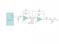
I have tested the Reimyo DAP 777 and Benchmark DAC1 output at 10 Khz, both can reproduce the sine wave almost perfectly ( Both are OS DACS ) So i have decided to improve the buffer stage of my TDA for better filtering above 22Khz . In the first opamp stage i have used 2K feedback resistor and 1nF filter cap, this one is a light filter . In the second opamp stage i have used 15K feedback resistor and 470pF cap, from the formula (1/2pRC ) it makes 22.5 Khz . Now DAC output looks like more to sine wave and the sound is more clean . "Bold" signature mostly gone...
Last edited:
Hi rehad,
With increasing frequency, fewer samples are available when running in NOS (without digital brickwall filter), at 20 KHz there are approx. 2 samples left to reconstruct the signal, at 5 KHz there would be approx. 9 samples.
This results in the step-shaped signal that becomes more clearly visible at higher frequencies.
This "problem" can be solved by using a very steep (digital) brickwall filter, that adds extra samples (interpolation) and cuts everything above say 20 Khz.
If we could hear frequencies up to say 100KHz these step shaped signals would sound pretty bad (inter-modulation). But our auditory system cuts everything above approx. 20 KHz, similar to a brickwall filter.
Simple analogue filters don't reconstruct sine wave shape like brickwall filters do, they only add phase distortion and cause trebles roll-off. The trebles roll-off can be corrected with filters that boost amplitude at higher frequencies, but the phase errors remain.
Every brickwall filter requires an analogue reconstruction filter at the DAC output, since this filter also introduces phase errors, these systems aren't perfect either. I have seen some DAC chips that compensate for external reconstruction filter phase errors, but then specified circuit (with Op-amps) needs to be used.
Most modern DAC chips often have integrated switched-capacitor reconstruction filters.
With digital audio, the biggest problem however seems to be timing (errors).
According the Shannon's law theoritecally sampling two times of the maximum frequency of the original signal is enough but this is not the case in practical situation. 44.1 Khz is enough for low frequencies but not enough for above 8 Khz . You simply get stepping square signal for high frequencies not a sine wave . This is the way what TDA1541 is doing nothing else . So I think Martti is right .
With increasing frequency, fewer samples are available when running in NOS (without digital brickwall filter), at 20 KHz there are approx. 2 samples left to reconstruct the signal, at 5 KHz there would be approx. 9 samples.
This results in the step-shaped signal that becomes more clearly visible at higher frequencies.
This "problem" can be solved by using a very steep (digital) brickwall filter, that adds extra samples (interpolation) and cuts everything above say 20 Khz.
If we could hear frequencies up to say 100KHz these step shaped signals would sound pretty bad (inter-modulation). But our auditory system cuts everything above approx. 20 KHz, similar to a brickwall filter.
Simple analogue filters don't reconstruct sine wave shape like brickwall filters do, they only add phase distortion and cause trebles roll-off. The trebles roll-off can be corrected with filters that boost amplitude at higher frequencies, but the phase errors remain.
Every brickwall filter requires an analogue reconstruction filter at the DAC output, since this filter also introduces phase errors, these systems aren't perfect either. I have seen some DAC chips that compensate for external reconstruction filter phase errors, but then specified circuit (with Op-amps) needs to be used.
Most modern DAC chips often have integrated switched-capacitor reconstruction filters.
With digital audio, the biggest problem however seems to be timing (errors).
I'm compiling a list of affordable DACs here: List of DACs Under $450 - AudioKarma.org Home Audio Stereo Discussion Forums
http://www.diyaudio.com/forums/digital-line-level/161845-list-dacs-under-450-a.html - diyaudio
Does this DAC have a PCB? What is the approximate build cost?
If you ask me about the cost of this DAC , its about 150 usd for the time being but its not finalised yet . If you want to imagine, take the digital part of the Lesha's DAC and use two serial opamps ( OPA627 and AD843 ) in the analog section ( not any tube staff ). Other thing about the power supply ; In each power rail ripple voltage is quite minimal ( below 1mv ) because i have used too much capacitor ( around 60,000 uF in total )
Hi rehad,
With increasing frequency, fewer samples are available when running in NOS (without digital brickwall filter), at 20 KHz there are approx. 2 samples left to reconstruct the signal, at 5 KHz there would be approx. 9 samples.
This results in the step-shaped signal that becomes more clearly visible at higher frequencies.
This "problem" can be solved by using a very steep (digital) brickwall filter, that adds extra samples (interpolation) and cuts everything above say 20 Khz.
If we could hear frequencies up to say 100KHz these step shaped signals would sound pretty bad (inter-modulation). But our auditory system cuts everything above approx. 20 KHz, similar to a brickwall filter.
Simple analogue filters don't reconstruct sine wave shape like brickwall filters do, they only add phase distortion and cause trebles roll-off. The trebles roll-off can be corrected with filters that boost amplitude at higher frequencies, but the phase errors remain.
Every brickwall filter requires an analogue reconstruction filter at the DAC output, since this filter also introduces phase errors, these systems aren't perfect either. I have seen some DAC chips that compensate for external reconstruction filter phase errors, but then specified circuit (with Op-amps) needs to be used.
Most modern DAC chips often have integrated switched-capacitor reconstruction filters.
With digital audio, the biggest problem however seems to be timing (errors).
I see your points Ecdesigns , thanks for the explanations,
May be i should use a external clocking circuit . Do you think that can give a major improvement ?
I want to build a tube SRPP output stage and I need some good regulator,
I seek help in choosing the best regulator , with less ripple and high noise rejection and stability etc ;
1. Janus regulator
2. Aikido solid stage regulator , the da-1 or something
3.diy-gene on ebay : LS-57, or LS-65
4. Lampizator style with 5U4C diode , CL(C//R)LC --- or CL(C//R)RC
5. Lampizator style with semiconductors diodes like vishay + caps+res
Dear -EC-,
Please allow me to go OT here--> I have received multiple mails from forum mates and good friends concerned by my own health and my family's well being following the terrible earthquake that my beloved country suffered last friday night. I thank you all for your kind interest and I asure you that I am OK, working hard as usual and all my relatives are fine. Fortunatelly for us the earthquake's epicenter was 600km to the north: here in Osorno, in the south of Chile, it was "only 6 to 7 degrees", but boy, I was there in Santiago on the last earthquake in 1985, which was a 7.8 (if I remember correctly) and the last one (6 to 7) was felt here even harder than the 1985 quake...
The centre of the country has zones that are devastated and we are reorganizing to send help to the unfortunate. There are around 730 casualties to the date and some coast villages (tourism and fishing) were totaly swipped because of a sunami that followed the movement. The experts say that it is very improbable that another quake occurs, because of the waste of stored energy which was massive, there must be little tension between plaques now...I hope so.
End of OT.
Thanks EC.
Best wishes,
M.
Please allow me to go OT here--> I have received multiple mails from forum mates and good friends concerned by my own health and my family's well being following the terrible earthquake that my beloved country suffered last friday night. I thank you all for your kind interest and I asure you that I am OK, working hard as usual
and all my relatives are fine. Fortunatelly for us the earthquake's epicenter was 600km to the north: here in Osorno, in the south of Chile, it was "only 6 to 7 degrees", but boy, I was there in Santiago on the last earthquake in 1985, which was a 7.8 (if I remember correctly) and the last one (6 to 7) was felt here even harder than the 1985 quake...The centre of the country has zones that are devastated and we are reorganizing to send help to the unfortunate. There are around 730 casualties to the date and some coast villages (tourism and fishing) were totaly swipped because of a sunami that followed the movement. The experts say that it is very improbable that another quake occurs, because of the waste of stored energy which was massive, there must be little tension between plaques now...I hope so.
End of OT.
Thanks EC.
Best wishes,
M.
Hi maxlorenz,
Good to hear you, your family and relatives are doing fine, I was worried about you and your family after hearing about an earthquake and following tsunami in Chile. Yesterday I happen to see that you were online (gmail) so I figured you must be ok. The pictures and coverage of this earthquake on the internet show the extent of damage. More earthquakes took place in Chile. Valdivia earthquake in Chile May 22 1960 was the largest ever instrumentally recorded. It measured a 9.5 on the Moment Magnitude (Mw) scale, but registered only an 8.5 on the Ms scale. Other earthquakes followed like the one you mentioned in March 3 1985.
I hope there won't be any after shocks and Chile gets sufficient help from other countries in order to quickly recover from this catastrophe.
Dear -EC-,
Please allow me to go OT here
Good to hear you, your family and relatives are doing fine, I was worried about you and your family after hearing about an earthquake and following tsunami in Chile. Yesterday I happen to see that you were online (gmail) so I figured you must be ok. The pictures and coverage of this earthquake on the internet show the extent of damage. More earthquakes took place in Chile. Valdivia earthquake in Chile May 22 1960 was the largest ever instrumentally recorded. It measured a 9.5 on the Moment Magnitude (Mw) scale, but registered only an 8.5 on the Ms scale. Other earthquakes followed like the one you mentioned in March 3 1985.
I hope there won't be any after shocks and Chile gets sufficient help from other countries in order to quickly recover from this catastrophe.
Hi,
Yes, at least we are world champions in one thing
Also, the earthquake on Chillan, on January the 23th of 1939, led 30.000 dead...it was a X on Mercalli's. I have an old patient that was a voluntary there in brigades to stop the criminal looting of the city's stores and houses...he says hundreds were killed this way and there were not locals...I am affraid that this fenomemon has repeated in the cities devastated, but the socialist governement was slow in reacting, maybe because curfew ("toque de queda") was one of the memories of the past military regime...the fact is that my country has the means and the people to solve this emergency (though it has to get rid of the bad guys) but any friendly help is very welcome.
Hi all,
Here a little review on John's new 1541A DAC module. I proberly am the first again who has it playing at home, like the 1543 DAC, which i reviewed a few weeks ago.
Let's start to say that the price of this DAC is not really in the DIY area. For a complete module with Superclock and honeycomb resistor you pay 617 euro. I had some serious doubt to buy it, because the 1543 DAC is already incredible good. I could be satisfied with it's sound. After John mailed me that his 1541A prototype sounded 'fantastic' i got curious. He did the proposal to buy and try it and if send it back when the difference is to close with the 1543.
The 1541A DAC module can be feed with 3x12 volt sources. In my case i use 3 leadaccu's 12V. I2S is coming from a batterie feeded full modded soundblaster reciever. I use a additional reclocker for DATA and WS.
After a few hours listening i can say this; this DAC is another level. The level of detail is about the same, but there is more/tighter bass, more control, more dynamic and what's special: more 'emotion'! If i should try to be critical at this first listening experience, i can't find any flaw's. It's listening fun of the highest level. For this moment i rate it above the best sound i ever heard, the LINN Klimax.
This DAC will stay in my system. The most important reason to keep it is the warm, emotional and full body sound. And looking at the price of the highly rated Altmann DAC, this dac is half of its price. In that sight it's a very acceptable price for this toplevel of sound.
Attachments
Thanks Brubeck.
Dear EC,
You converted me into a "low noise voltage reference believer"
The sound improvement of your Vref ( even if mine are not exactly as yours; cheaper maybe... ) both with active and passive outputs is outstanding! With my passive I used some Pana FC as caps (left-over parts) and with my active I used my preference: Rubycon ZL 1500uF each. The bass is huge with the active output now. I think the type and value of the capacitors here is important.
I received by coincidence this article (1/3 part) about the importance of the accuracy and noise performance of the Vref for ADCs (which I presume is comparable to DACs for this purpose):
TechOnline
I use a three LED approach to divide from V+.
Given that I only mannaged to have 3.5VDC as reference, I may have lower dynamic "roof"(?), What do you think? What others problem may I face?
Anyway, I ordered a big amount of coils to imitate your Vref.
Cheers,
M.
Hi brubeck,
Thanks for this review,
I have adapted (lowered) price for the complete TDA1541A DAC module. The module now includes wirewound Mobius / Honeycomb passive I/V resistors, 4-crystal superclock and TDA1541A DAC chip for eur 399 vat exclusive.
I use the SD-transport to drive the DAC modules and with this very clean source I clearly notice more detail and refinement when using the TDA1541A module, although the new TDA1543 DAC module comes closer now.
The universal power supply for both TDA1541A and new TDA1543 DAC modules is now completed. It allows for both, mains and battery powered operation. It's also designed to power SD-transport and small universal remote control receiver module (being developed).
The existing TDA1543 DAC module has been redesigned (simplified) while performance could even be increased. Price of this DAC module could be reduced too. The module now has on-board regulator and can be directly connected to a 8 ... 12V battery power supply.
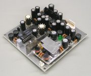
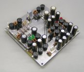
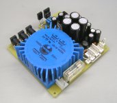
I attached pictures of TDA1541A DAC module, new TDA1543 DAC module, and universal mains / battery power supply.
Thanks for this review,
For a complete module with Superclock and honeycomb resistor you pay 617 euro. I had some serious doubt to buy it, because the 1543 DAC is already incredible good.
I have adapted (lowered) price for the complete TDA1541A DAC module. The module now includes wirewound Mobius / Honeycomb passive I/V resistors, 4-crystal superclock and TDA1541A DAC chip for eur 399 vat exclusive.
I use the SD-transport to drive the DAC modules and with this very clean source I clearly notice more detail and refinement when using the TDA1541A module, although the new TDA1543 DAC module comes closer now.
The universal power supply for both TDA1541A and new TDA1543 DAC modules is now completed. It allows for both, mains and battery powered operation. It's also designed to power SD-transport and small universal remote control receiver module (being developed).
The existing TDA1543 DAC module has been redesigned (simplified) while performance could even be increased. Price of this DAC module could be reduced too. The module now has on-board regulator and can be directly connected to a 8 ... 12V battery power supply.
I attached pictures of TDA1541A DAC module, new TDA1543 DAC module, and universal mains / battery power supply.
Attachments
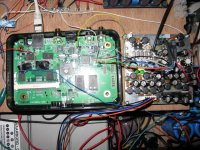
Oops! Apparently I made another D1 NOS DAC...
Why another DAC? might some ask...because I have two jobs and I need two portable NOS DACs , that's why. There are always good excuses to build...
See some photos; I needed something very little to be used in that small and strong iron speaker box.
Picasa Web Albums - mauricio
I made it with a wall-wart supply: the good thing is that I can test the "stepped rectifier" circuit with it.
Picasa Web Albums - mauricio
Attenuators incorporated. SuperTeddyRegulated DAC. Passive output. I am afraid that no honeycombs will fit inside...
Picasa Web Albums - mauricio
It does sound pretty good, for one day of hard work...
Cheers,
M.
Why another DAC? might some ask...because I have two jobs and I need two portable NOS DACs
, that's why. There are always good excuses to build...See some photos; I needed something very little to be used in that small and strong iron speaker box.
Picasa Web Albums - mauricio
I made it with a wall-wart supply: the good thing is that I can test the "stepped rectifier" circuit with it.
Picasa Web Albums - mauricio
Attenuators incorporated. SuperTeddyRegulated DAC. Passive output. I am afraid that no honeycombs will fit inside...
Picasa Web Albums - mauricio
It does sound pretty good, for one day of hard work...
Cheers,
M.
Oh! Thank you very much for your encouragement. The truth is that in vivo the thing is not so precise and clear...
I used Welwin RC55Y precision resistor as I/V R, that was the best I had around.
Yes, the PCBs are homemade; after all these years I finally learnt how to etch my own so I abandoned the "knife and dremel" method.
This is an easy and inexpensive project. I wonder if there are more builders around...
Cheers,
M.
Oh, well, given that I am now a "low noise Vref believer" I tried John's approach and installed one Vref to each I/V resistor in my humblest D1 NOS DAC: the one made of salvaged components...SMPS from a printer (just a choke previous the Vregs) TeddyRegs, DDDAC USB receiver (stock clock), common metal film resistor and Siemens output caps. The caps for the other Vref were salvaged from an old Technics cassette deck from the eighties
I connected the thing, preparing to hear subtle cues about improved channel separation...nothing subtle, I'm afraid, but evident openness of midrange and greater separation of instruments, plus more extension of the extremes.
Now I have to mod all my gear; I wonder if the hundred coils I ordered will be enough... I even will try this on power amps.
Apart, I have tried to source 52AWG enamel copper (around 100Ohm/meter) to make the honeycomb I/V resistors, without success. I found 48AWG to make the I/V resistors of the "scrambler/interpolator DAC" which I still love. Anybody knows a source for 52AWG enamel wire, that will sell reasonably low quantities of it?
Cheers,
M.
I connected the thing, preparing to hear subtle cues about improved channel separation...nothing subtle, I'm afraid, but evident openness of midrange and greater separation of instruments, plus more extension of the extremes.
Now I have to mod all my gear; I wonder if the hundred coils I ordered will be enough...
I even will try this on power amps.Apart, I have tried to source 52AWG enamel copper (around 100Ohm/meter) to make the honeycomb I/V resistors, without success. I found 48AWG to make the I/V resistors of the "scrambler/interpolator DAC" which I still love. Anybody knows a source for 52AWG enamel wire, that will sell reasonably low quantities of it?
Cheers,
M.
Filter Capacitor Types
Hello again,
I have completed the dac circuit and trying to make a tonal balance so the filter caps are not finalized yet . In the attached output schematic the capacitor value and the type is something very tricky. I have tried polyester and polypropylene caps . Polyester sounds too metallic and sound is too dry there is almost zero harmonic. So i have tried KP that time mids & highs are quite good but low end is too boomy , the gain get boosted in the lowend . The sound in total is not bad but it needs an improvement in the low frequencies. What can you suggest ? ( I have used 2x 470pF Ero KP caps to get 1nf , because i couldnt find a trusted 1nf MKP or KP capacitor in the electronic market , there are so many noname china caps which i don't rely )
Note : It needs at least 2 days for a new cap to burn & stabilize . So experiments take time
Thanks
Reha
Attachments
Last edited:
Hi maxlorenz,
Noise on Vref for the passive I/V resistors will end up on your audio signal. So filtering (using clean voltage) for Vref really helps. Same applies to TDA1543 power supply (TDA1543 has poor PSRR).
For power supply I now always use 3-stage stepped rectifiers, these greatly reduce (limit) switching noise bandwidth as these offer "soft switching". This has nothing to do with diode type (Schottky) or diode switching noise. Its the effect of switching on / off large capacitive loads like a smoothing cap.
Next I use a capacitance multiplier to reduce ripple voltage to below approx. 1mVpp using a Darlington stage.
After that, I use LC filtering (Hybrid chokes) to filter out residual noise). This un-stabilized, clean, ripple-free DC voltage is then fed to a plain 78xx / 79xx regulator. because the input voltage is a clean DC voltage, the plain regulators (with limited bandwidth) now function without problems and offer tight load regulation.
RF / HF regulation cannot be provided by the regulator and relies on local decoupling using suitable decoupling caps and / or power supply filters.
I use large capacitor values on the regulator output (470 ... 1500uF) to filter out regulator noise.
This approach no longer requires discrete (large bandwidth) regulators.
For highly critical circuits like reference voltages, masterclock and reclocker, I use additional LC filters. These take care of the noise that managed to pass the power supply.
Regarding your setup, one very important detail is still missing: extreme low sample timing jitter. I estimate that jitter amplitude of your current setup is somewhere between 200 and 1000ps rms (based on measurements I performed on similar interfaces and clocks). Good sound quality (transparency, speed, refinement) requires jitter levels that are at least factor 25 lower.
Jitter spectrum extends from sub-sonic into the MHz range, so it will affect deepest bass to highest trebles plus reflected mirror images that fold back into the audio range (NOS). Since there is no way of removing this jitter, or reducing it to acceptable levels, you can only shape it so sound becomes "acceptable".
required copper wire would be too thin to handle (it will snap the moment you attempt to wind the resistor). You might find this very thin copper wire in miniature relays or relays with high coil voltage (230V AC for example).
When using lacquered resistance wire like isachrome, wire diameter is only 0.08mm (100 Ohms / meter) and this is already very difficult to handle. Advantage is that this resistance wire is much stronger and won't break as easily compared to copper wire.
Copper wire also requires much more windings (given the lower resistance for same diameter). This means increased self capacitance of the diy I/V resistor. This is not optimal.
Oh, well, given that I am now a "low noise Vref believer" I tried John's approach and installed one Vref to each I/V resistor in my humblest D1 NOS DAC
Noise on Vref for the passive I/V resistors will end up on your audio signal. So filtering (using clean voltage) for Vref really helps. Same applies to TDA1543 power supply (TDA1543 has poor PSRR).
For power supply I now always use 3-stage stepped rectifiers, these greatly reduce (limit) switching noise bandwidth as these offer "soft switching". This has nothing to do with diode type (Schottky) or diode switching noise. Its the effect of switching on / off large capacitive loads like a smoothing cap.
Next I use a capacitance multiplier to reduce ripple voltage to below approx. 1mVpp using a Darlington stage.
After that, I use LC filtering (Hybrid chokes) to filter out residual noise). This un-stabilized, clean, ripple-free DC voltage is then fed to a plain 78xx / 79xx regulator. because the input voltage is a clean DC voltage, the plain regulators (with limited bandwidth) now function without problems and offer tight load regulation.
RF / HF regulation cannot be provided by the regulator and relies on local decoupling using suitable decoupling caps and / or power supply filters.
I use large capacitor values on the regulator output (470 ... 1500uF) to filter out regulator noise.
This approach no longer requires discrete (large bandwidth) regulators.
For highly critical circuits like reference voltages, masterclock and reclocker, I use additional LC filters. These take care of the noise that managed to pass the power supply.
Regarding your setup, one very important detail is still missing: extreme low sample timing jitter. I estimate that jitter amplitude of your current setup is somewhere between 200 and 1000ps rms (based on measurements I performed on similar interfaces and clocks). Good sound quality (transparency, speed, refinement) requires jitter levels that are at least factor 25 lower.
Jitter spectrum extends from sub-sonic into the MHz range, so it will affect deepest bass to highest trebles plus reflected mirror images that fold back into the audio range (NOS). Since there is no way of removing this jitter, or reducing it to acceptable levels, you can only shape it so sound becomes "acceptable".
Apart, I have tried to source 52AWG enamel copper (around 100Ohm/meter) to make the honeycomb I/V resistors, without success.
required copper wire would be too thin to handle (it will snap the moment you attempt to wind the resistor). You might find this very thin copper wire in miniature relays or relays with high coil voltage (230V AC for example).
When using lacquered resistance wire like isachrome, wire diameter is only 0.08mm (100 Ohms / meter) and this is already very difficult to handle. Advantage is that this resistance wire is much stronger and won't break as easily compared to copper wire.
Copper wire also requires much more windings (given the lower resistance for same diameter). This means increased self capacitance of the diy I/V resistor. This is not optimal.
- Home
- Source & Line
- Digital Line Level
- Building the ultimate NOS DAC using TDA1541A