Hi,
Forgive me for going back onto the dem reclock!
I have just implimented this mod to my player.
I am using /2 (5.6448Mhz) of the master clock for bitclock (pin 2)and subsequent DEM. I am using ecdesigns diagram posted a couple of pages ago.
BCK, inveted and non inverted (inverted via NAND gate,both input pins connected together) both via 10k, both have 2k2 to the -15v rail.
From what I have read, should the bitclock be /4 (2.8224Mhz)?
It is working fine, but am I missing a trick by running/2 instead of /4?
Its sounding pretty awesome btw
FYI I also feed the system clock directly to pin 4 on the DAC.
Many Thanks for all the info shared here.
Ian
Hi, I've had another listen today and I'm pretty certain of a problem.
I heard distortion on a track. The vocals at the start of Imagine by Eva Cassidy. I swapped over to my CD63 and the distorion is not on the recording. The distortion always happens at roughly the same place. I say roughly because its not exactly the same place in the recording each time.
Does this mean the DEM reclock is not locking properly at certain freq? Should I get the bit clock to /4 of the system clock?
Thanks Ian
Hi UV101
The DEM clock frequency has limits (max. frequency around 7 MHz), so 5.6448 MHz is close to the limit. It's better to decrease DEM clock to 2.8224 MHz. If the TDA1541A still doesn't sync (tolerances), the DEM clock frequency can be further reduced.
In order to make sure the DEM system works correctly, you have to test with low level recordings (Sheffield Lab / AT2B "My Disc"). When the DEM system syncs, sound should be crystal clear, when it doesn't, low level recordings sound highly distorted as bit errors increase significantly.
I am using /2 (5.6448Mhz) of the master clock for bitclock (pin 2)and subsequent DEM. I am using ecdesigns diagram posted a couple of pages ago.
BCK, inveted and non inverted (inverted via NAND gate,both input pins connected together) both via 10k, both have 2k2 to the -15v rail.
From what I have read, should the bitclock be /4 (2.8224Mhz)?
It is working fine, but am I missing a trick by running/2 instead of /4?
The DEM clock frequency has limits (max. frequency around 7 MHz), so 5.6448 MHz is close to the limit. It's better to decrease DEM clock to 2.8224 MHz. If the TDA1541A still doesn't sync (tolerances), the DEM clock frequency can be further reduced.
In order to make sure the DEM system works correctly, you have to test with low level recordings (Sheffield Lab / AT2B "My Disc"). When the DEM system syncs, sound should be crystal clear, when it doesn't, low level recordings sound highly distorted as bit errors increase significantly.
Hi ecdesigns,
Many Thanks! I'll try it at 2.8224Mhz later.
I was hoping that being an S2 chip, it would cope ok but I guess not. It does seem very good most of the time but I picked it up listening to an older analogue recording (with tape hiss for added character ).
Whats your thoughts on Pin 4? It used to be master clock on non A versions. The sound improved quite a bit when I put the sys clock onto pin4 on the A ver S2.
Ian
Many Thanks! I'll try it at 2.8224Mhz later.
I was hoping that being an S2 chip, it would cope ok but I guess not. It does seem very good most of the time but I picked it up listening to an older analogue recording (with tape hiss for added character
).Whats your thoughts on Pin 4? It used to be master clock on non A versions. The sound improved quite a bit when I put the sys clock onto pin4 on the A ver S2.
Ian
Hi UV101,
TDA1541 pin4:
DATA left channel input (pin 27 connected to -5V, simultaneous mode).
System Clock input (pin 27 connected to GND or +5V, time MUX mode).
TDA1541A pin4:
DATA right channel input (pin 27 connected to -5V, simultaneous mode).
Not used (pin 27 connected to GND or +5V, time MUX mode).
Unused inputs must be connected either to GND or VCC. When leaving an unused input unconnected, it could pick-up interference. In this case, it's most likely that pin4 will pick-up interference from pin3 (DATA).
Whats your thoughts on Pin 4?
TDA1541 pin4:
DATA left channel input (pin 27 connected to -5V, simultaneous mode).
System Clock input (pin 27 connected to GND or +5V, time MUX mode).
TDA1541A pin4:
DATA right channel input (pin 27 connected to -5V, simultaneous mode).
Not used (pin 27 connected to GND or +5V, time MUX mode).
Unused inputs must be connected either to GND or VCC. When leaving an unused input unconnected, it could pick-up interference. In this case, it's most likely that pin4 will pick-up interference from pin3 (DATA).
Hi EC,
In the case of TDA1543, what is the best way to handle pin7?
(in your D1M)
Thanks,
M
Unused inputs must be connected either to GND or VCC. When leaving an unused input unconnected, it could pick-up interference. In this case, it's most likely that pin4 will pick-up interference from pin3 (DATA).
In the case of TDA1543, what is the best way to handle pin7?
(in your D1M)
Thanks,
M
Hi maxlorenz,
TDA1543 pin7 is both input and output, it outputs a reference voltage for an external OP-amp (datasheet page 3 and page 5), and can also be used to control the TDA1543 internal bias current. This is done by connecting either a resistor or constant current source between pin7 and GND.
In the D1M, TDA1543 pin7 is not connected.
In the case of TDA1543, what is the best way to handle pin7?
TDA1543 pin7 is both input and output, it outputs a reference voltage for an external OP-amp (datasheet page 3 and page 5), and can also be used to control the TDA1543 internal bias current. This is done by connecting either a resistor or constant current source between pin7 and GND.
In the D1M, TDA1543 pin7 is not connected.
-ecdesigns- said:Hi UV101
The DEM clock frequency has limits (max. frequency around 7 MHz), so 5.6448 MHz is close to the limit. It's better to decrease DEM clock to 2.8224 MHz. If the TDA1541A still doesn't sync (tolerances), the DEM clock frequency can be further reduced.
In order to make sure the DEM system works correctly, you have to test with low level recordings (Sheffield Lab / AT2B "My Disc"). When the DEM system syncs, sound should be crystal clear, when it doesn't, low level recordings sound highly distorted as bit errors increase significantly.
Hi ecdesigns,
I can report that the /2 to the dem is working correctly!
The distortion I heard was resonation of ornaments on a shelf in the room!

I think the overall dynamics and seperation are that much better now that I have noticed deficiencies in my listening enviroment!
Sorry for the red herring!
Ian
-ecdesigns- said:Hi UV101,
TDA1541 pin4:
DATA left channel input (pin 27 connected to -5V, simultaneous mode).
System Clock input (pin 27 connected to GND or +5V, time MUX mode).
TDA1541A pin4:
DATA right channel input (pin 27 connected to -5V, simultaneous mode).
Not used (pin 27 connected to GND or +5V, time MUX mode).
Unused inputs must be connected either to GND or VCC. When leaving an unused input unconnected, it could pick-up interference. In this case, it's most likely that pin4 will pick-up interference from pin3 (DATA).
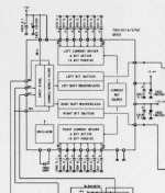
Found this on a old thread about S2's. It says they were all produced for Marantz CD7's and the diagram shows pin 4 as sck.
http://www.diyaudio.com/forums/showthread.php?postid=1807175#post1807175
I've also read sevaral articles that stating that the sysclock input was still used in A ver chips
This was a very big improvement for me
Attachments
Hi UV101,
My Sony CD player has a plain TDA1541, it also has pins 2 and 4 connected. I think this is done for compatibility, so both TDA1541 and TDA1541A work in the same PCB without PCB modification.
I can't imagine Philips would have changed the TDA1541A-S2 chip function for Marantz, only chip grading (selection).
If you connect pin 4 to GND (Time multiplex mode), and you still have sound, it's obvious that this pin has no function in this mode (it's not used to clock the output latches).
However, it's possible that applying clock signals to pin4 (that is capacitively coupled to the TDA1541A internal circuits when not used), could affect on-chip interference levels, and I assume this would also be audible.
So the effect you are experiencing could be a change in interference levels at the DAC analogue outputs.
Found this on a old thread about S2's. It says they were all produced for Marantz CD7's and the diagram shows pin 4 as sck.
My Sony CD player has a plain TDA1541, it also has pins 2 and 4 connected. I think this is done for compatibility, so both TDA1541 and TDA1541A work in the same PCB without PCB modification.
I can't imagine Philips would have changed the TDA1541A-S2 chip function for Marantz, only chip grading (selection).
If you connect pin 4 to GND (Time multiplex mode), and you still have sound, it's obvious that this pin has no function in this mode (it's not used to clock the output latches).
However, it's possible that applying clock signals to pin4 (that is capacitively coupled to the TDA1541A internal circuits when not used), could affect on-chip interference levels, and I assume this would also be audible.
So the effect you are experiencing could be a change in interference levels at the DAC analogue outputs.
Today I tried replacing the Solen 6.8uF (bypassed with MKP1837) with the GAD-viva AZ125 PP cap. It was like blow me away with the sound that is so natural and with realism.
I dun know why my dac needs some 'dischage' before it can start playing. It seems there is some capacitive load at the DAC TDA1541a or the SAA7220. Only after pressing it, then it can start playing music. Do I need to put in the ground bounce circuit (5x100R and the 330R to the TDA1541a ?)
I dun know why my dac needs some 'dischage' before it can start playing. It seems there is some capacitive load at the DAC TDA1541a or the SAA7220. Only after pressing it, then it can start playing music. Do I need to put in the ground bounce circuit (5x100R and the 330R to the TDA1541a ?)

Hi CCschua,
Looks like you have the same DAC as I am using as a "test" for some of the things that are being suggested on this Thread by ECDesigns.
depending on your source, you may want to try this sync reclocker for the slim devices squeezebox:
http://audiogestalt.wordpress.com/
all credit to John Swenson for the above
This totally transformed this DAC, to an even greater degree that any of the other mods I have tried.
Out of interest, where did you hear about the GAD-Vifa caps - have you tried the VH Audio Teflon equivalents?
Brad
I got to know GAD-viva from one of the stockist in Singapore. It is available from diygene at ebay. I have not tried the VH but I know it is one of the best. ECdesign is using the VCAP TFTF. Perhaps OIMP may fit the bill or even the Jensen copper could perform very well too.
Hi EC,
Thanks for your answer (post 2807).
Today I tried an attenuator for I2S direct from PCM2706 (2V signals) on my humble D1M. I ended up with 1K2 series resistor, 3K3 from "signal node" to the DAC's +3,4V supply and 680R from node to ground. This was done empirically as I did not know how to solve it
DATA signal is now 600mV and sound is cleaner.
Any advice is welcome...
Thanks,
M
Hi maxlorenz,
3K3 / 1K values are for 5V power supply, so the modification you made was necessary when using a 3.4V power supply.
Meanwhile I improved the BCK attenuator / jitter reduction circuit, only few parts required.
SD-player design is almost completed. First an extreme low jitter 11.2896 MHz masterclock was needed, I constructed a master clock with discrete components that runs on multiple 11.2896 MHz crystals, and uses an external 3V alkaline battery reference voltage (oscillator only draws 150nA, so the battery will last very long). During testing it became clear that the battery reference was required to get best transparency and focus. I didn't succeed in constructing a suitable mains-powered reference voltage.
The SD-card player sound quality (while running on this new master clock) is simply stunning, SPDIF is absolutely no match for this, no matter what jitter blocker is used in the DAC, even slaving the transport won't provide results like this.
With this clean digital audio source, I was able to easily determine the best performing I/V converter, as the sound is highly transparent, revealing everything.
Well, the best performer (to my surprise) is plain passive I/V conversion with resistors, ignoring TDA1543 output compliance. I use a single TDA1543 DAC chip, 2 x 680 Ohm I/V resistors connected to a 3V alkaline battery reference voltage. This gives me 2 x 1.56Vpp without using the Vref pin. I did try connecting both a resistor and a CCS from Vref to GND in order to shift bias current to obtain sine wave output with very low distortion (at 1.56Vpp). But anything connected to Vref greatly degraded sound quality, So that's why I used a 3V reference voltage instead.
The 1.56Vpp output voltage amplitude is plenty to drive my MOSFET power amp that has a gain of 50, close to clipping. The power amp is fully DC-coupled, and I only use 2 x 1uF coupling caps in the entire signal path. Power amp input impedance is approx. 100 K Ohm. I connected the DAC output straight to my power amp (no conventional volume control anymore).
Volume was now controlled by variable power resistors in series with the speakers.
Even at whispering low volume settings, sound is crystal clear and highly detailed (maximum resolution regardless of volume setting).
Hum and noise are totally inaudible, even when listening very close to the speaker.
I plan to use digitally controlled power attenuators (relays and power resistors) that are placed as close to the speakers as possible, this also results in far less critical speaker interlinks. Both L and R attenuator modules are driven by a central control unit with remote control.
Any advice is welcome...
3K3 / 1K values are for 5V power supply, so the modification you made was necessary when using a 3.4V power supply.
Meanwhile I improved the BCK attenuator / jitter reduction circuit, only few parts required.
SD-player design is almost completed. First an extreme low jitter 11.2896 MHz masterclock was needed, I constructed a master clock with discrete components that runs on multiple 11.2896 MHz crystals, and uses an external 3V alkaline battery reference voltage (oscillator only draws 150nA, so the battery will last very long). During testing it became clear that the battery reference was required to get best transparency and focus. I didn't succeed in constructing a suitable mains-powered reference voltage.
The SD-card player sound quality (while running on this new master clock) is simply stunning, SPDIF is absolutely no match for this, no matter what jitter blocker is used in the DAC, even slaving the transport won't provide results like this.
With this clean digital audio source, I was able to easily determine the best performing I/V converter, as the sound is highly transparent, revealing everything.
Well, the best performer (to my surprise) is plain passive I/V conversion with resistors, ignoring TDA1543 output compliance. I use a single TDA1543 DAC chip, 2 x 680 Ohm I/V resistors connected to a 3V alkaline battery reference voltage. This gives me 2 x 1.56Vpp without using the Vref pin. I did try connecting both a resistor and a CCS from Vref to GND in order to shift bias current to obtain sine wave output with very low distortion (at 1.56Vpp). But anything connected to Vref greatly degraded sound quality, So that's why I used a 3V reference voltage instead.
The 1.56Vpp output voltage amplitude is plenty to drive my MOSFET power amp that has a gain of 50, close to clipping. The power amp is fully DC-coupled, and I only use 2 x 1uF coupling caps in the entire signal path. Power amp input impedance is approx. 100 K Ohm. I connected the DAC output straight to my power amp (no conventional volume control anymore).
Volume was now controlled by variable power resistors in series with the speakers.
Even at whispering low volume settings, sound is crystal clear and highly detailed (maximum resolution regardless of volume setting).
Hum and noise are totally inaudible, even when listening very close to the speaker.
I plan to use digitally controlled power attenuators (relays and power resistors) that are placed as close to the speakers as possible, this also results in far less critical speaker interlinks. Both L and R attenuator modules are driven by a central control unit with remote control.
-ecdesigns- said:
Well, the best performer (to my surprise) is plain passive I/V conversion with resistors, ignoring TDA1543 output compliance
Welcome to the club.
The better a system gets the less you can live with active stuff in the chain.
If you'd start fiddling around with 100db/SPL speakers, problems/improvements get even more obvious. (That's my experience)
Interesting to see that you start working with batteries. ( We had this discussion half a million posts back).
Volume control is another issue. If you allign overal gain in the chain to the SPL of the speaker, you can easily live with 6-12db on a 24bit signal. (I do understand that 24bit is a problem for your setup
) I for sure would never put powerresitors in the chain.Cheers
After much thinking and troubleshooting, I finally come to piece and pieces with the simple transimpedance circuit.
I notice using T2 = k117 gives good resolution but the whole spectrum sounded bright. After a while, the sound is dry and not involving.
So I gather my feet and with the arrival of 20 piece pack of 2sc2240, I began to place them onto the breadboard piece by piece to ensure Idac is almost zero, follow by T2. This is a tedious process but it has to due to different Vbe.
I am close to it. T2 is easier to match and T1 is the most 'sensitive'. I am still having about 15mV +- 3mV when running. Though tempted to put a CCS, I still think the best is to make it simple. And really the ground has the most abundant noise. I cant even put in the decoupling cap to the power supply.
After everything is done, it is music in the air. As compared to k117, I found 2sc2240 (with mirror at T2) more musical, singer has more emotions, more bass and mid bass details and liquid smooth.
- Home
- Source & Line
- Digital Line Level
- Building the ultimate NOS DAC using TDA1541A