Corrected/Updated Schematic
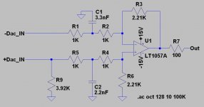
Here is a correction to the non-servo schematic, changes would also apply to the servo version.
This improves HF balance between inverting and non-inverting inputs and corrects input impedance imbalance as well.
Soundwise
Currently I am using this version with LM4562NA. I will add the servo circuitry once I have the required 1uF film caps.
Note: If you have already built it as previously shown I wouldn't bother to make all of the changes shown here, their effect would be largely inaudible. I do recommend correcting the value of R9 so that the load presented to the dac op-amps is relatively close to identical. (Particularly important if input coupling caps are used - which I don't recommend btw.)
Attachments
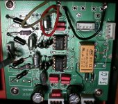
Here is the best picture I can manage with the digital camera I currently own. I used a tripod and a 600W tungsten photoflood, were I to do this on film I would have been able to get great results, but this 10yr old digicam isn't really up to this level of photography.
NOTE: I have edited the picture so that it is oriented in the way that I am referring to parts in the post. Hope this makes things clearer.
Install wire jumpers where the two 1nF film caps used to be. (They connect to pin 5 of the op-amps and need to be grounded since the servo mod is not being done.)
Note that there are a bunch of resistors removed, and the 2.2nF Wimas have been replaced. (This is optional, but recommended.)
TOPSIDE from back to front (back being where the rca jacks are connected.)
1. Remove all the 47uF/100uF and 0.1uF input caps.
2. Towards the top left corner are 3 resistors 1K, 100K, and 1K remove these, next is 2.2nF which you can replace with a better one if desired, finally there is another 1K which should be removed.
3. To the immediate left of each op-amp are two resistors and a cap. If you are replacing the resistors remove them and the cap carefully. Install from left to right 1K, 1K, 2.21K (where the 47pF cap used to be)
4. To the right of each op-amp are two resistors, clip these out.
5. Remove the 1K and 100K at the bottom lower left corner of the board.
6. Remove the 2K resistors mounted directly behind the op-amps towards back of board.
7. Remove all 4 resistors directly to the right of the input connector from the digital board.
8. Refer to the picture to orient and solder the new input resistors - this eliminates some unneeded traces from the signal path.
The caps closest to the op-amps should be 3.3nF, (middle 2 of the 4) and the two closer to the board edges should be 2.2nF if you are replacing them.
Resistor locations that will not be reused just clip the leads, otherwise carefully remove the component from locations that will be reused and wick the solder out carefully. Pads lift quickly on this board.
Install wire jumpers where the two 1nF film caps used to be. (They connect to pin 5 of the op-amps and need to be grounded since the servo mod is not being done.)
BOTTOM SIDE
Solder a 2.21K resistor from pin 3 of each IC to the ground plane.
Solder the 100 ohm resistors to pin 1 and not pin 6 as shown in the older photos some posts back.
Attachments
Thanks Kevin. In the process of trying these mods.
What are the values of the input resistors you refer to? From the top of your picture down, can you please specify the values of the 6 resistors down the left edge? I think they probably are 1K, ?, 1K, 1K, ?, 1K based on the schematic.
Also, you mention several 2.21K resistors. Is that value critical or can I reuse the 2K resistors I removed from the board?
I also see you removed the two 22uF caps down at the borrom of the board where the old ferrites were, but did not specify those in your inctructions.
Bob
Hi Bob,
All of the other resistors are 1K as you surmised with the exception of the two 3.92K resistors used to make the non inverting input impedance the same as the inverting inputs.
1K 3.92K 1K 1K 3.92K 1K
You can reuse the 2K resistors you removed, but you will need all 4 of them obviously. The 2.21K provide some additional needed gain, but it isn't otherwise an issue.
I strongly recommend replacing every single resistor with Holco ($0.45 each from Michael Percy) or the even better Caddock MK-132 at $3.95 each from Digikey or Michael Percy. I'm using the older Holco, and availability of some values in the older style construction is limited. You can use 1.02K or 1.05K, but they must all be the same, and matching to 0.1% isn't a bad idea. (Same deal for the 2.21K - need more gain then use 2.49K)
The cap removals you mention are covered in an earlier mod I posted a week or so ago. All of the caps on my board were 47uF or 100uF. Cap values listed on the silk screen more often than not are wrong on these boards. Standard grade Black Gate 47uF/50V are what I used everywhere. The originals were rated at 16V, not enough margin imo for good life on 15V supplies.
Incidentally I am happy to report it still sounds good two days after the original mod, usually long past the point where I've concluded that it doesn't. It is immediately obvious - no warm up required.
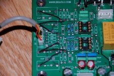
Thanks Kevin. I've marked out the connection locations for those resistors in the attached photo. I think this is correct per your board photo, but just to be sure could you please take a look?
Also what type of caps are you using for the 3.3nF and 2.2nF?
Bob
Also what type of caps are you using for the 3.3nF and 2.2nF?
Bob
Attachments
Hi Bob,
Your pix is exactly correct.. Please leave it up for others to follow..
One straggler resistor at right angles to the ones remaining needs to be removed..
Several parts as mentioned go on the back side of the board, and definitely reconfigure the relay to shunt for mute rather than the way it is arranged stock if you haven't already.
Caps correct as originally stated.
Hi Bob,
See post #233 for the relay shunt connections, just be sure to solder the op-amp end of the 100 ohm resistors to pin 1 of each op-amp and not pin 7. Using the stock connectors no other changes are necessary beyond what is mentioned in the original post.
Solder 2.21K from pin 3 to nearby ground.
I'm using polystyrenes from Xicon. (Digikey)
nhuwar said:Hey Kevin next time you want to take some good digital pictures let me know. I will bring my tripod and my digital slr and let you try it out .
Then you will want another new toy LOL
Nick
Hey Nick,
I was thinking just that thought this afternoon as I was experimenting with my old photofloods and tripod.
I think you'll be impressed with the improvement, it's quite a bit better than the last time you were here. The Sony incidentally got quite a large upgrade this week-end as well, so the frame of reference has moved too..
I'll have spend some time on the turntable and riaa amplifier soon..
Member
Joined 2003
Hi kevin,
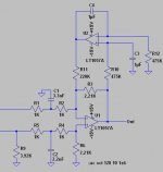
Been busy this weekend and haven't had any time to look at this. I am just running the circuit simulation today, and it looks like your filter has a very shallow rolloff (as expected). What are your thoughts as to leaving in the 2K and 1nF cap at the output of the op-amp, so that the filter transfer function is closer to what is in the datasheet for AD1852? Keep in mind that I really don't know the requirements for a DAC output filter.
Been busy this weekend and haven't had any time to look at this. I am just running the circuit simulation today, and it looks like your filter has a very shallow rolloff (as expected). What are your thoughts as to leaving in the 2K and 1nF cap at the output of the op-amp, so that the filter transfer function is closer to what is in the datasheet for AD1852? Keep in mind that I really don't know the requirements for a DAC output filter.
DcibeL said:Hi kevin,
Been busy this weekend and haven't had any time to look at this. I am just running the circuit simulation today, and it looks like your filter has a very shallow rolloff (as expected). What are your thoughts as to leaving in the 2K and 1nF cap at the output of the op-amp, so that the filter transfer function is closer to what is in the datasheet for AD1852? Keep in mind that I really don't know the requirements for a DAC output filter.
It doesn't appear to be necessary and I suspect that eliminating that last op-amp stage can't hurt.
If you need more attenuation you can change those input caps as long as you maintain the ratio.
FWIW that 1nF cap does not appear to be of very good quality either.
PSU
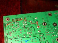
Hi Kevin,
just want to double check the mods for the psu. In red is a mod I did yesterday following your comments, did not take away the conn1 yet but did also disconnect the top trace to the cap. ( in red in the picture)
Circled in blue are components where you can see the tiny vias ( as an example) : what do you suggest, to connect a wire to the adjacent plane instead of these tiny vias? ( see blue line? )
Thanks for help!
Attachments
Hi C37,
Yes what you show is correct. I didn't bother with those particular vias, the ones that are most important are associated with a long set of traces in the +/-15V analog supply which are actually grounded at multiple vias.. Just scrape away some of the solder mask and solder to the adjoining ground plane. I chose the locations where the output caps are located to do this. Arguably overkill. You could do as many as you can stand - definitely won't hurt.
I did solder a small piece of braid between the grounded standoff locations and the adjoining ground plane.
Conn1 is probably the very most important change I made on the psu board. Be sure to sever all connections to the ground plane on both sides of the board right at the 4th pin from the left. (transformer center tap.)
Hi Kevin,
Thanks for the fast answer! In my pic posted right before= the center tap goes to the 4th connector from the left too, if I cut the bottom trace ( which I haven’t yet) as well as the top ( that one I did: the one that goes to the cap), then the center tap is not connected to anything???
Or are there some hidden connection beneath the plastic conn1?
Regards,
Thomas
Well, I made the most recent set of changes and ... nothing blew up (that's always good news). I can say immediately that the imbalance between the top end and the midrange is gone. There even appears to be a bit more bass punch than before.
I have a couple of meetings to attend this morning but I expect to give it more listen time later this afternoon. I think I'll have to swap the OPA2107's with the LM4562's to see which sounds better in this new configuration, now that everything has changed so drastically.
Thanks again Kevin for working out the details of this new design.
Bob
- Status
- This old topic is closed. If you want to reopen this topic, contact a moderator using the "Report Post" button.
- Home
- Source & Line
- Digital Line Level
- Zhaolu DAC - a good value DAC?