Yes. There is a small delay between two channel.
banana said:how do u split Left and right data? By inverting Fsync??
Attachments
Thank you, Hartono.
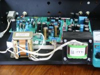
I design the PCB in 3 separate module so it has great flexibility. Receiver, main and analog modules, each has a separate power supply on board. As such the DAC and analog modules can be changed/upgraded easily.
The receiver module includes relocking. It is powered by the very low noise regulator REG104-5 from Burr Brown. The shift registers can be configure easily to be compatible with various data formats.
Hartono said:Looks nice")
Hi Dean
The PCM63 DAC is not yet ready to compete with my tda1541a. Certain parts used in the PCM63 are not as goods as I would like, most importantly the XO. I have not been able to find a decent XO for the PCM63. Some resitors in the analog stage are cheap Chinese parts. It's not fully break-in.
The strong point that can easily be heard in the PCM63 is more precise, excellent frequency extension and well controlled bass. It's surprisingly smooth sounding for its mosfet analog stage.
At the moment, my TDA1541a still has the advantage in term of musicality. I have never stopped upgrading it.
deandob said:Quantran,
I believe previously you had a TDA1541 NOS DAC (same one I use, twin TDA design) - I'd be interested in your assessment of your new DAC in NOS vs the TDA1541?
Regards,
Dean
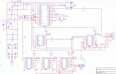
For those who wants to use PCM63 in NOS mode, this is the schematic for the receiver module. It works perfectly. Sounds great!!!
J2 is out signal to feed PCM63s
Pin 1: Serial Clock
Pin 3: LE Right
Pin 4: LE Left
Pin 5: Data
J1 is used for configuring the receiver module for 16 bit, 18 bit or 20 bit DAC. Adding one more 74HC164 will give the compatibility with 24 bit DAC e.g. pcm1704.
J2 is out signal to feed PCM63s
Pin 1: Serial Clock
Pin 3: LE Right
Pin 4: LE Left
Pin 5: Data
J1 is used for configuring the receiver module for 16 bit, 18 bit or 20 bit DAC. Adding one more 74HC164 will give the compatibility with 24 bit DAC e.g. pcm1704.
Attachments
Sorry Jos
I've been very busy with work. The DAC is working very well but now I am too lazy to make new PCB. I changed the design quite a bit.
The above schematic uses a 11.2896mhz oscillator with a divider using 74hc74 chip because I could not find 2.8224mhz at that time. Now I changed to 2.8224mhz and one inverter (removed 74hc74) because this design needs one additional inverted serial clock.
The PCM63 chips are now powered by TL3080 regulator. Huge improvement over LM317/337.
I learnt many experience fine tuning this DAC ... I will try to help by answering questions if anyone want to built one but I don't plan to make PCB in the near future.
I use the 74hc164 chips to shift fsync by 20 bck cycles. One chip can shift 8 cycles only so 3 chips are required for 20 cycles because pcm63 is 20 bit dac.
In the first time i tried to shift data but the fsync edge could not synchronise with data by this method which resulted in static noise in one channel? So i changed to shifting fsync rather than data signal. Shifting fsync work flawlessly.
It's hard to tell if removal of 74hc74 made a real difference because the 11.2896 osc used with 74hc74 was a generic one (no jitter spec) while the 2.8224mhz i am using now is a Tent labs branded osc. The sound of the dac with the tent labs osc is better.
Last edited:
Updated schematic CS8412/4 --> PCM56/58/63
Attached is the schematic for use with 2,8224mhz osc. Actually the serial clock generated by cs8412/4 may be use if you don't want an OSC.
Jumper J1 is for selection of word length
1-2: 20 bits
3-4: 18 bits
5-6: 16 bits
Attached is the schematic for use with 2,8224mhz osc. Actually the serial clock generated by cs8412/4 may be use if you don't want an OSC.
Jumper J1 is for selection of word length
1-2: 20 bits
3-4: 18 bits
5-6: 16 bits
Attachments
- Status
- This old topic is closed. If you want to reopen this topic, contact a moderator using the "Report Post" button.
- Home
- Source & Line
- Digital Line Level
- Cs8412 - Pcm63 Non-oversampling